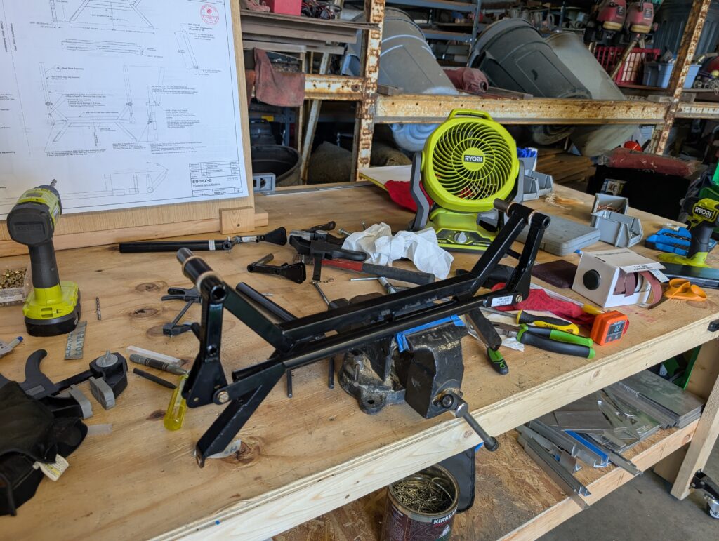
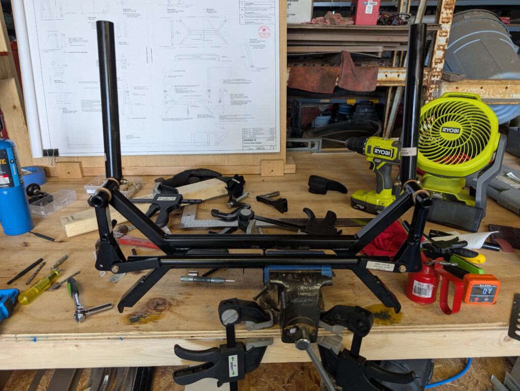
Set bushings into top of control stick frame with Loctite 638. Using new taper reamer, reamed LH stick grip hole and inserted taper pin. Repeated whole process for right hand stick grip and found that sticks were not parallel with control horns and cross link tube would not fit in between left and right control sticks. In order to properly fit link rod, both control sticks would be tilted 5 degrees outward. Suspect that control sticks slightly twisted when initially drilling shafts. Decided to redo control sticks with spare control horns from original kit. Removed powder coating from new control horns and lubricated with white lithium grease. Inserted horns into the control stick frame and squared them up using digital level. Attached link rod to RH horn and drilled 3/16″ pilot hole in link rod for LH horn. Enlarged hole and installed SF-610-3 bushing into link rod. Rechecked squareness of assembly; checked good. Installed SF-812-3 bushings into lower pivot points of control frame. Realigned LH control horn to vertical position and placed existing control stick onto horn shaft. Clamped control stick to piece of scrap wood to keep it square with assembly. Drilled approximate taper pin hole size on both sides of shaft separately using existing holes in the control stick. Reverified squareness with assembly then finished hole off with (properly sized) taper reamer. Repeated process on RH side using opposite control stick to set vertical position of assembly. Temporarily reinstalled old taper pins to check assembly; both sticks vertical with link rod centered and no play in mechanisms. Will replace taper pins at later date.

Hours Worked: 4.37
Leave a Reply