Controls

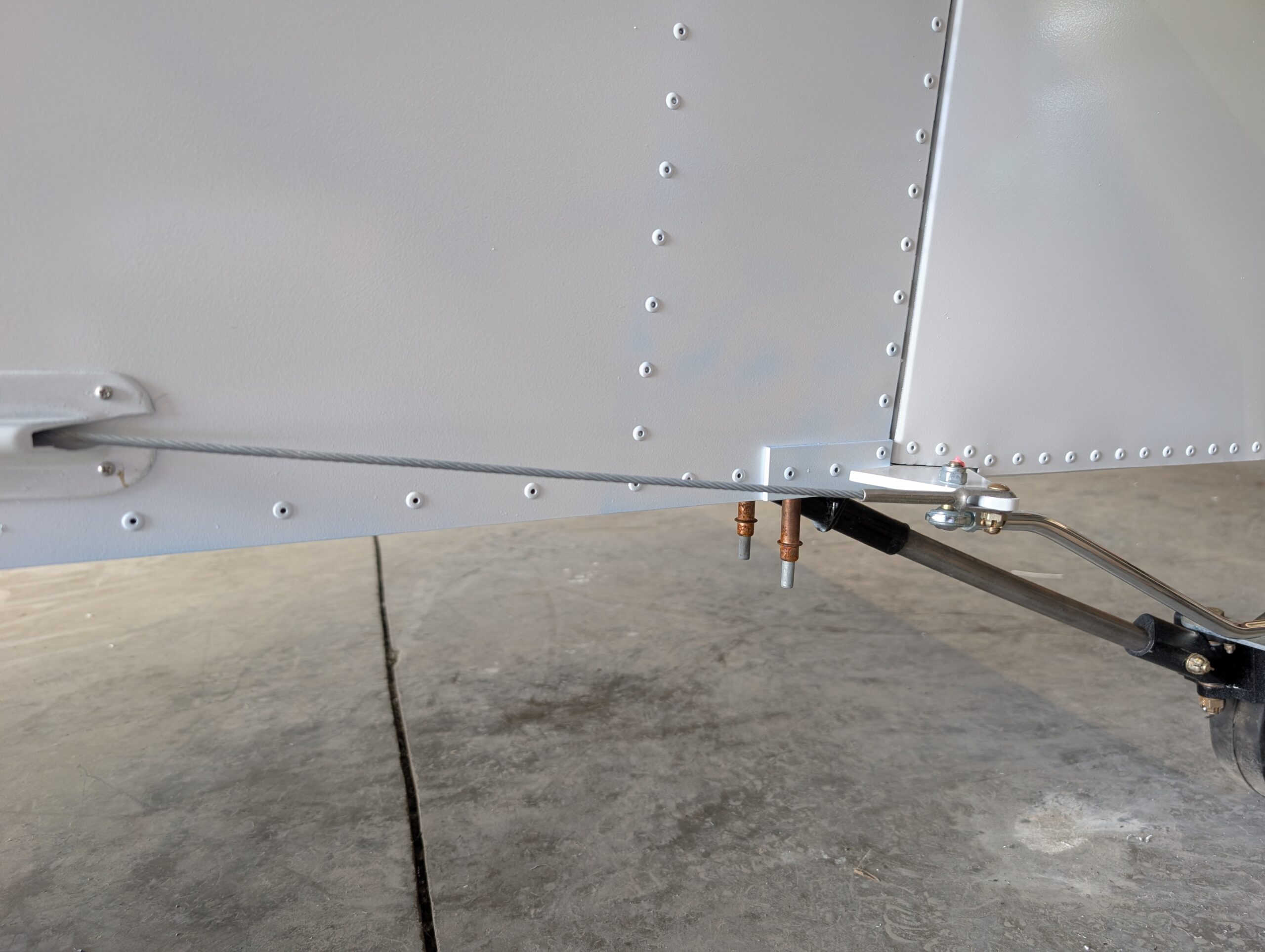
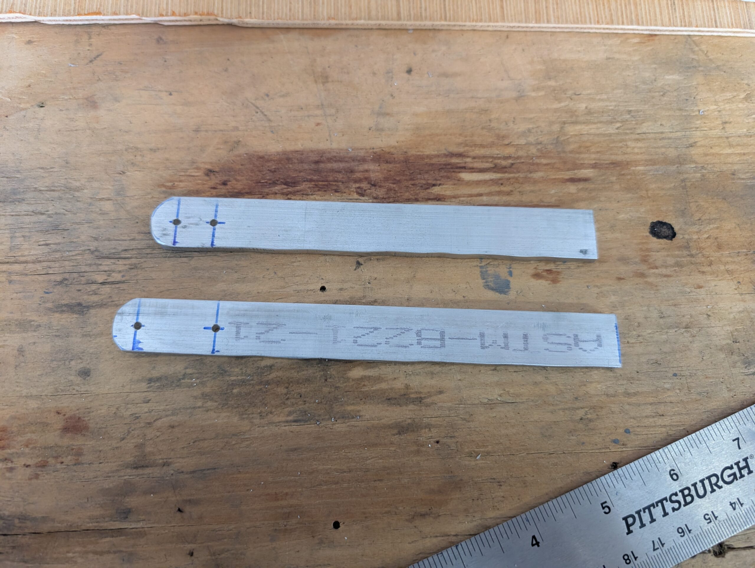
Aileron Rigging
Created aileron neutral alignment tool with two rulers similar to the one used for flap rigging. Set neutral position for RH aileron and centered stick assembly using digital level. Adjusted aileron pushrod length via rod ends then secured RH aileron to control stick. Repeated process for LH aileron. Verified freedom of movement and range of…
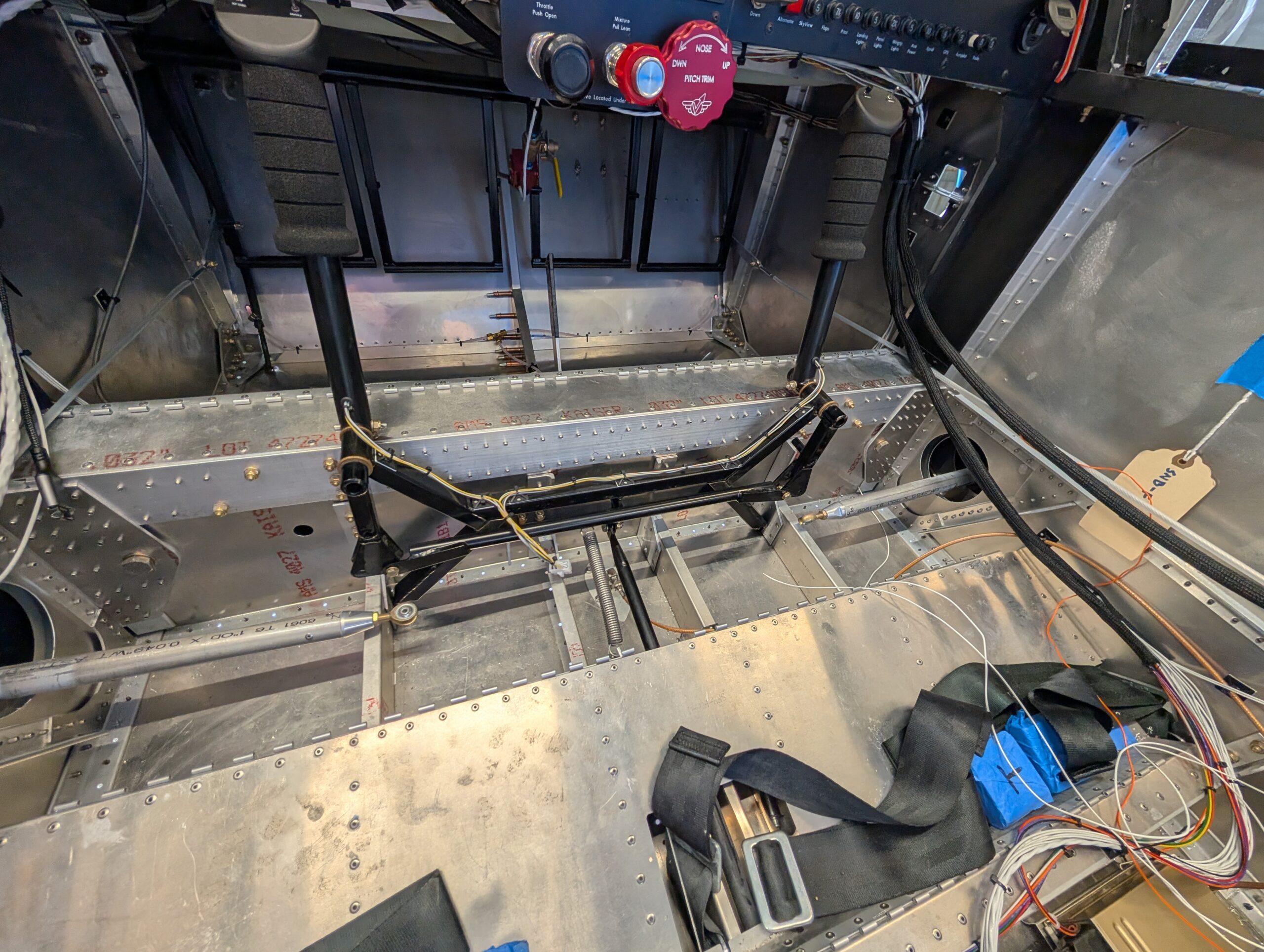
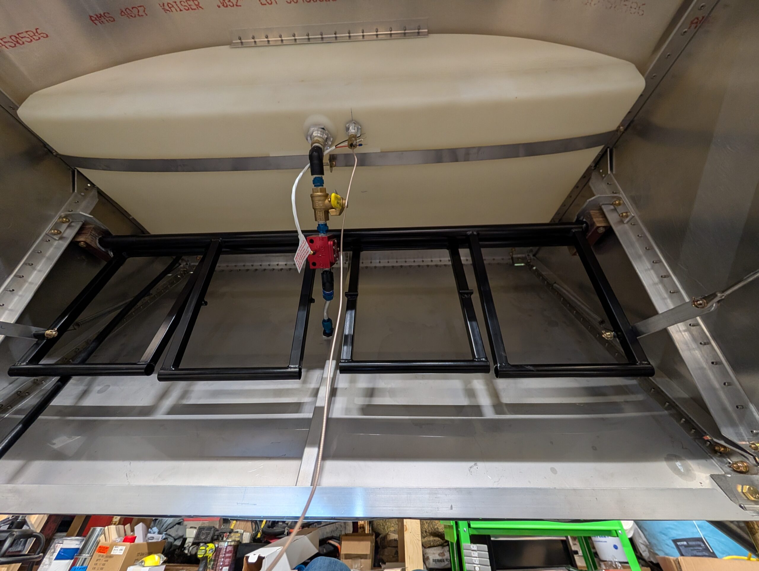
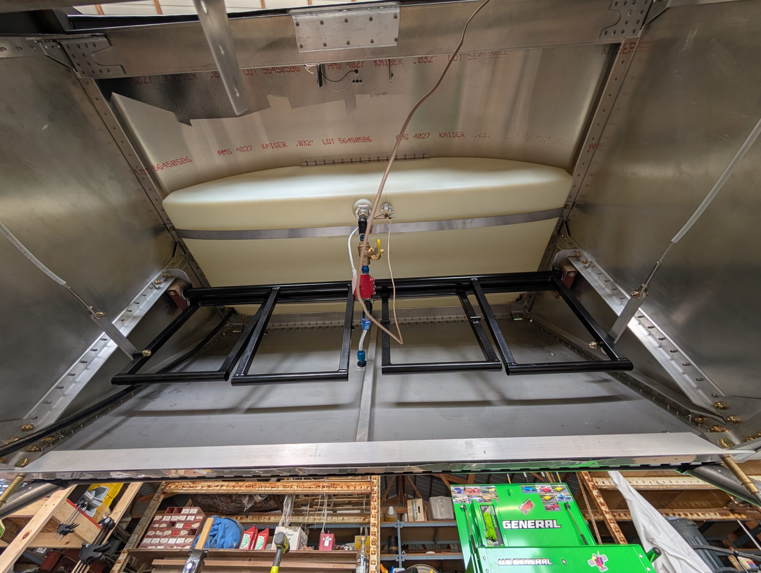
Control Frame Installation
Fabricated auto pilot push rod bracket from spare 2″ aluminum angle and bolted it to bottom LH side of control frame with AN3 hardware. Upon initial fit of the frame, discovered that aileron stops were contacting ends of spar tunnel bolts so trimmed approximately 3/8″ off each end of aileron stop. Stops still contact frame…
Elevator and Rudder Rigging
Connected rudder cables to rudder horn per plans and installed rudder cable fairings on fuselage. Installed hardware for elevator push rod and lubricated bushing with LPS-1. Riveted SNB-F23-09 pushrod assembly to fuselage and verified freedom of movement in elevator control system. Hours Worked: 1.05
Flap Rigging
Began rigging flaps for final installation by trimming flap pushrod length from 3″ to 2″ to allow more adjustment of rod ends. Removed flap motor from drive tube for easier access and started by testing position of LH flap. Adjusted lower pushrod end to achieve full-up flap neutral position of 2 59/64″ measured from the…
Rudder Control System – Part 2
Heated up C01-03 rudder spring stock with propane torch and bent springs to specs in plans. Previously tried to bend springs without heat and spring steel broke rather than bent. After installing springs into fuselage, discovered that plan dimensions were a little long and resulted in rudder pedals not returning to neutral. Shortened springs by…
Rudder Control System – Part 1
Installed rudder pedals and mount blocks into fuselage. Applied white lithium grease to rudder pedals before tightening rudder pedal mount blocks. Fed rudder cables through aft fuselage and temporarily installed AN23 clevis pins into rudder horn. Installed cable fairleads into fairlead blocks. Bolted cable adjusters onto rudder pedals and marked LH cable adjuster hole per…
Rudder System Prep – Part 2
Removed forward fuselage floor for better access to rudder pedals then removed rudder pedals and mounting blocks. Used die grinder to remove powder coating from pivot points on rudder pedals. Created cable adjusters from aluminum bar stock. Hours Worked: 1.62

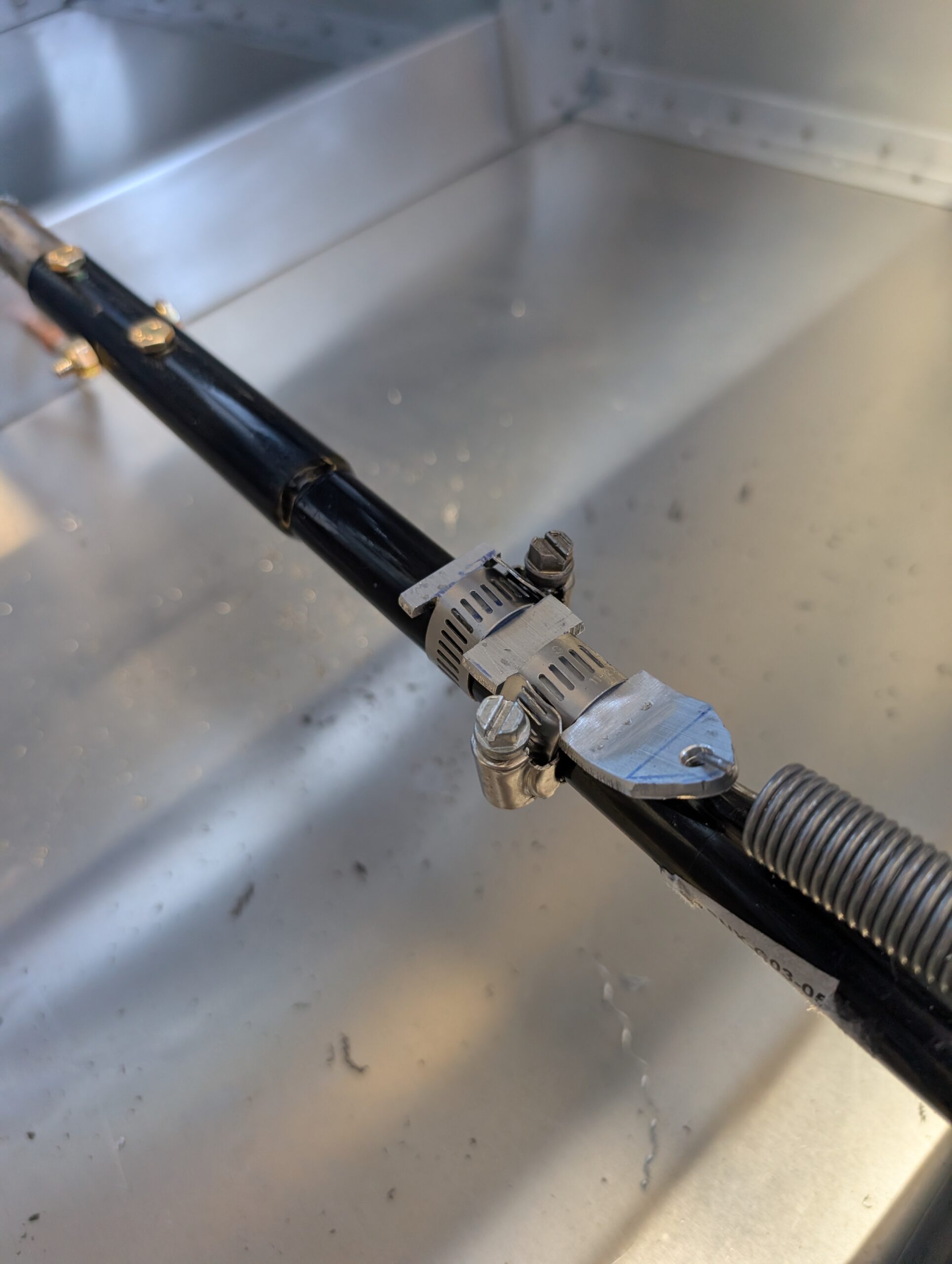
Trim System Installation – Part 2
Finished trim system by installing last clamp on elevator pushrod and balance spring. Will wait to adjust until flight testing occurs. Also added torque seal to elevator push rod bolts. Hours Worked: 0.32

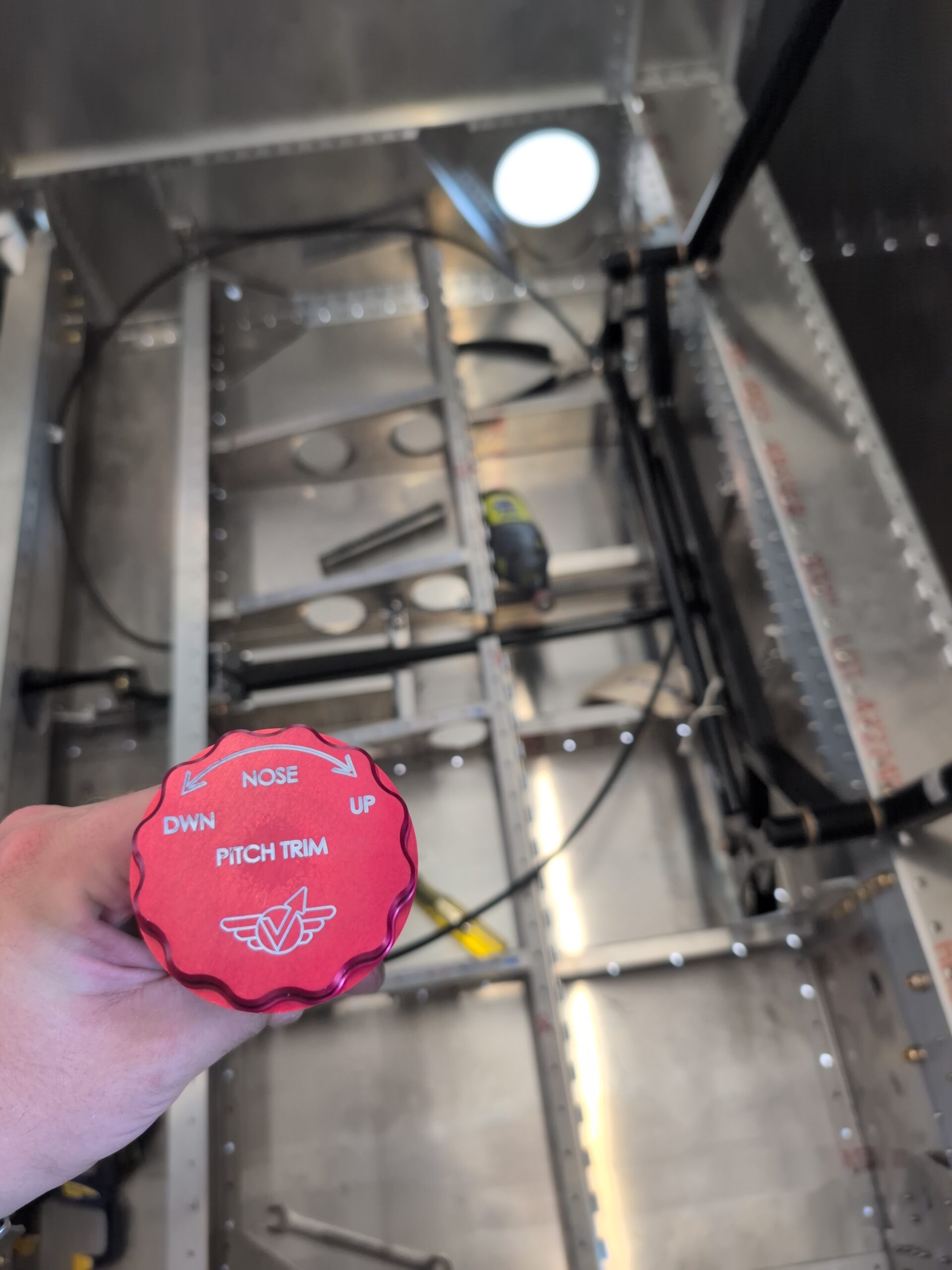
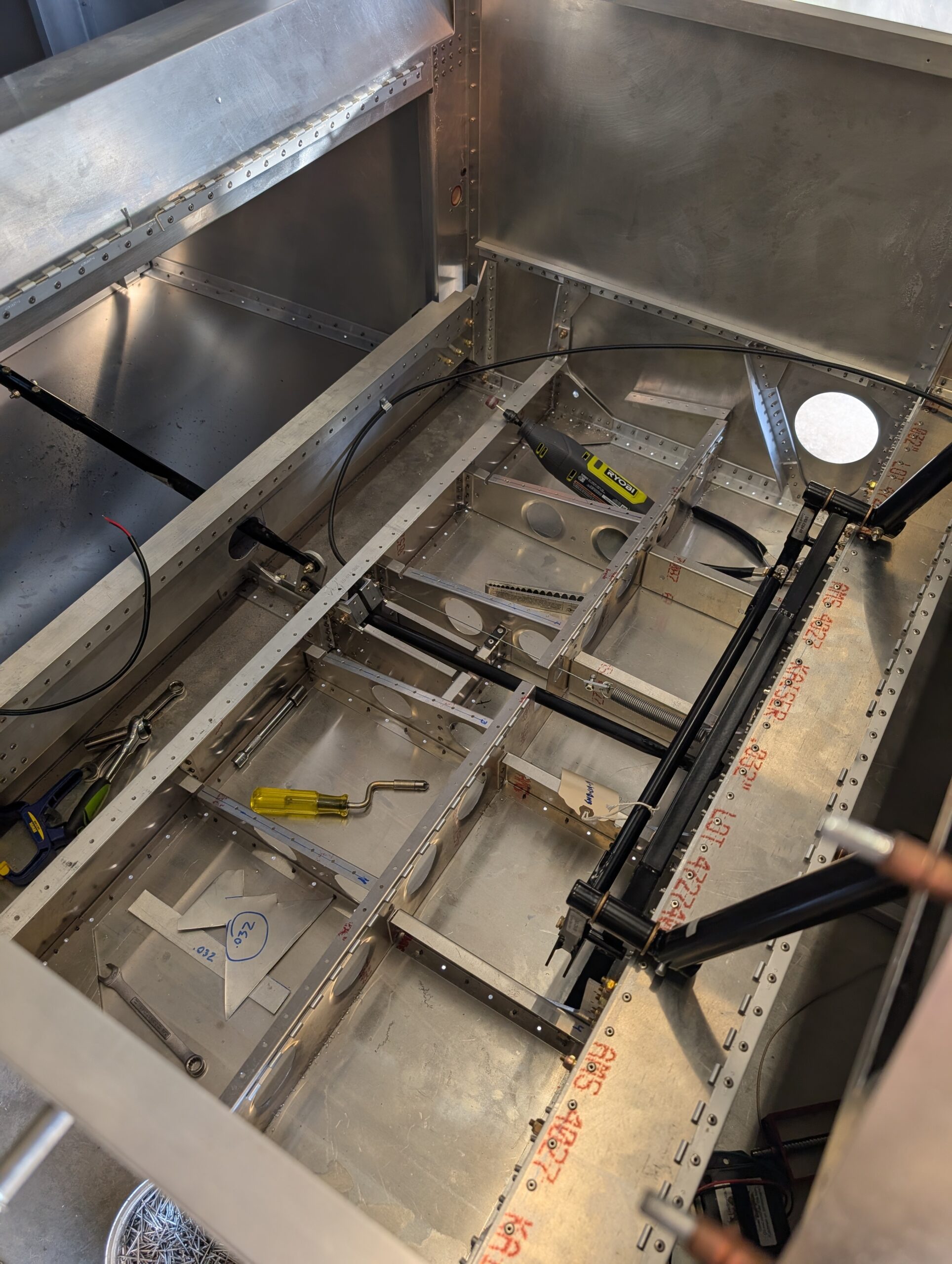
Trim System Installation – Part 1
Began trim system installation by removing lower instrument panel and drilling holes for throttle, mixture, and trim wheel. Measured and drilled hole for trim cable sleeve below seat pan. Mocked up cable run and trimmed around 18″ from cable and sleeve. Ran cable through trim adjuster and sleeve then secured to rear spar carry through…
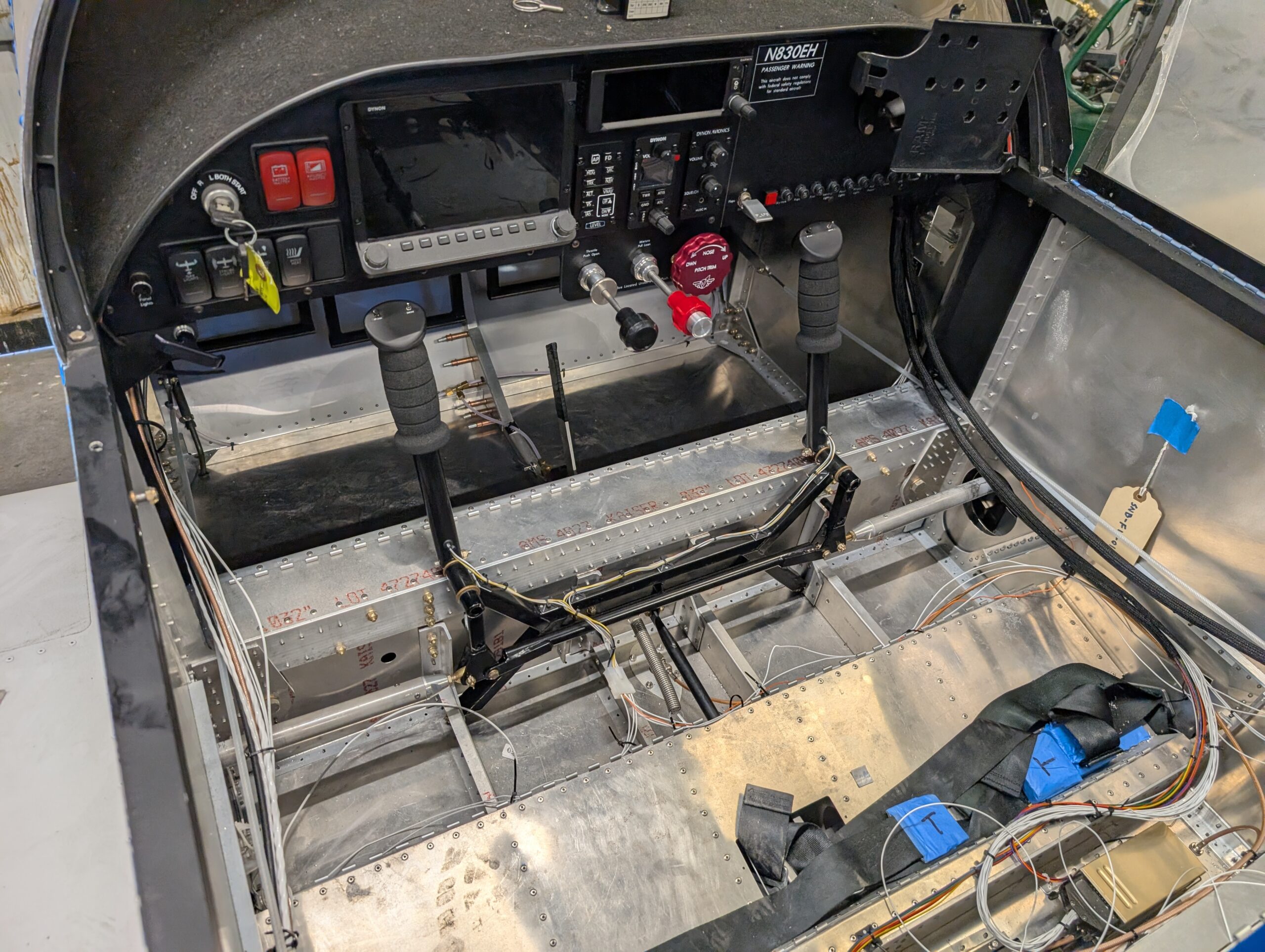
Elevator Control System – Part 1
Temporarily installed control stick assembly. Pressed SF-812-3 bushings into stick to idler bar and control frame then installed idler hardware permanently and stick hardware temporarily. Verified freedom of movement and clearances with idler bar. Pressed bushing into elevator push rod ends, clecoed forward pushrod support to cross ties, and checked clearance of elevator push rod.…
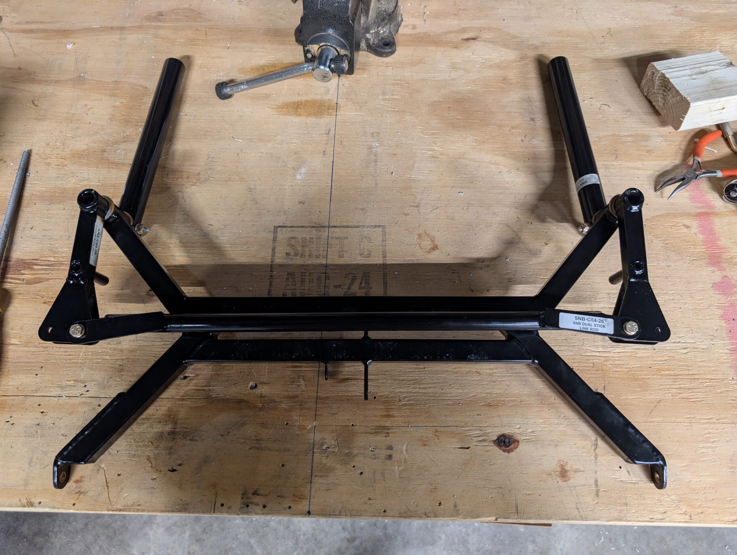
Control Stick Assembly – Part 3
Disassembled dual stick assembly and deburred stick holes. Lubricated control stick horns with lithium grease and deburred taper pin holes. Reassembled left and right control sticks and attached link rod with hardware. C04 complete! Hours Worked: 0.70
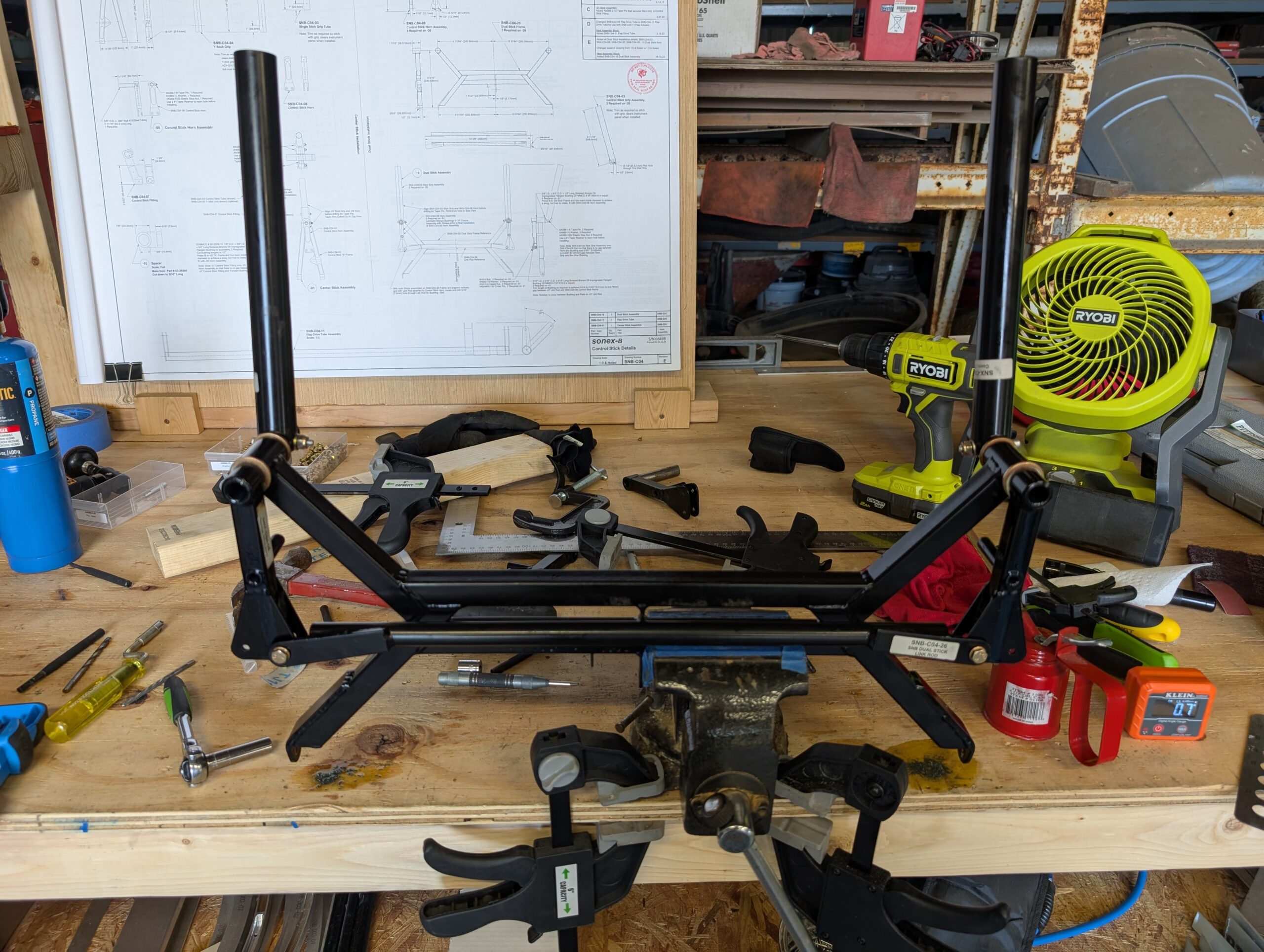
Control Stick Assembly – Part 2
Set bushings into top of control stick frame with Loctite 638. Using new taper reamer, reamed LH stick grip hole and inserted taper pin. Repeated whole process for right hand stick grip and found that sticks were not parallel with control horns and cross link tube would not fit in between left and right control…