emkrueger830

Panel Installation – Part 5
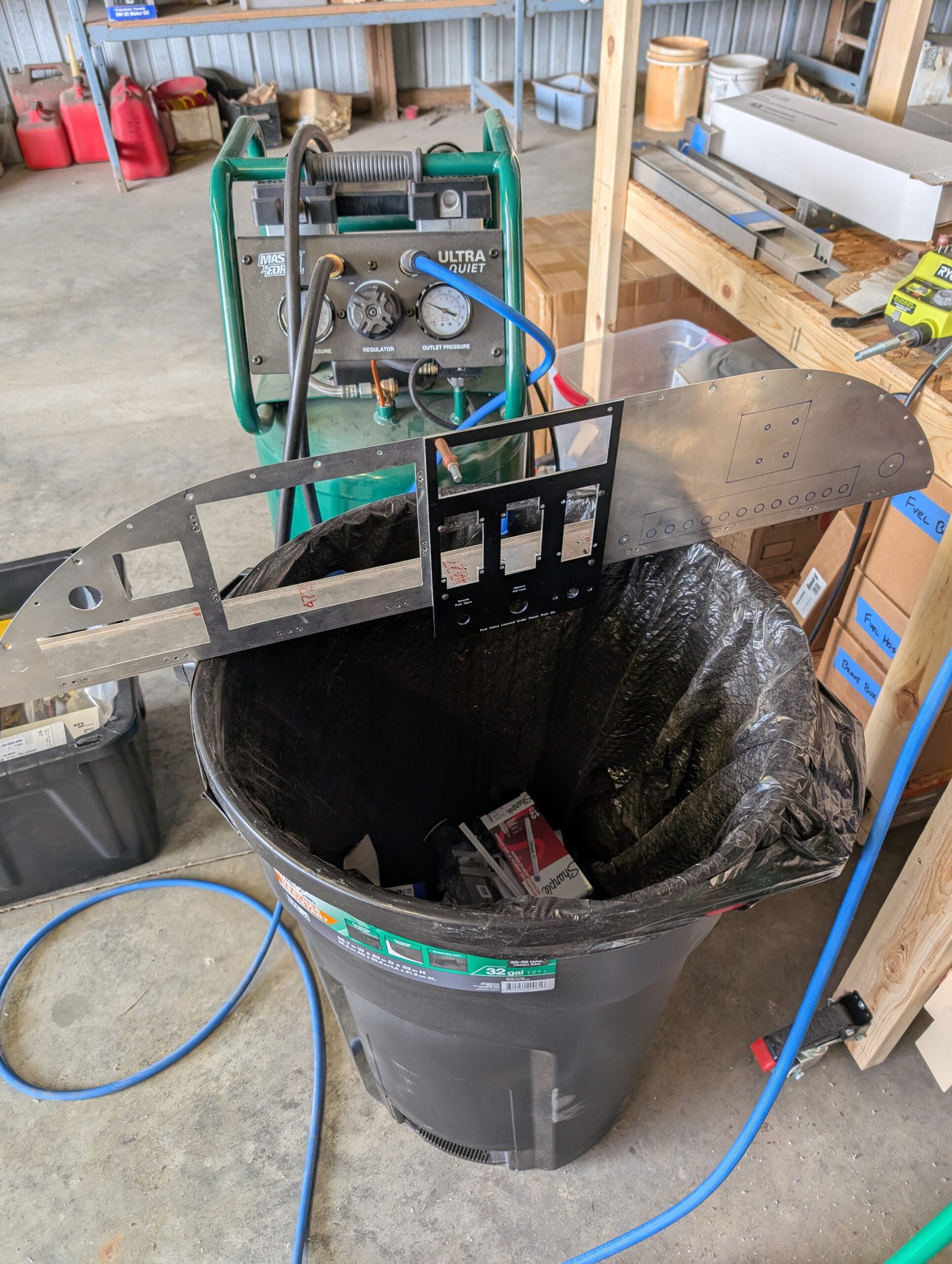
Located GPS175 tray brackets onto tray and marked hole locations. Drilled screw holes into side brackets then installed 8-32 nutplates. Attached brackets to tray and mocked up location on panel backer. Updrilled bracket attach holes then prepped brackets and panel backer for flush rivets. Riveted GPS175 mounting tray to panel backer. Drilled out holes for…

Panel Installation – Part 4
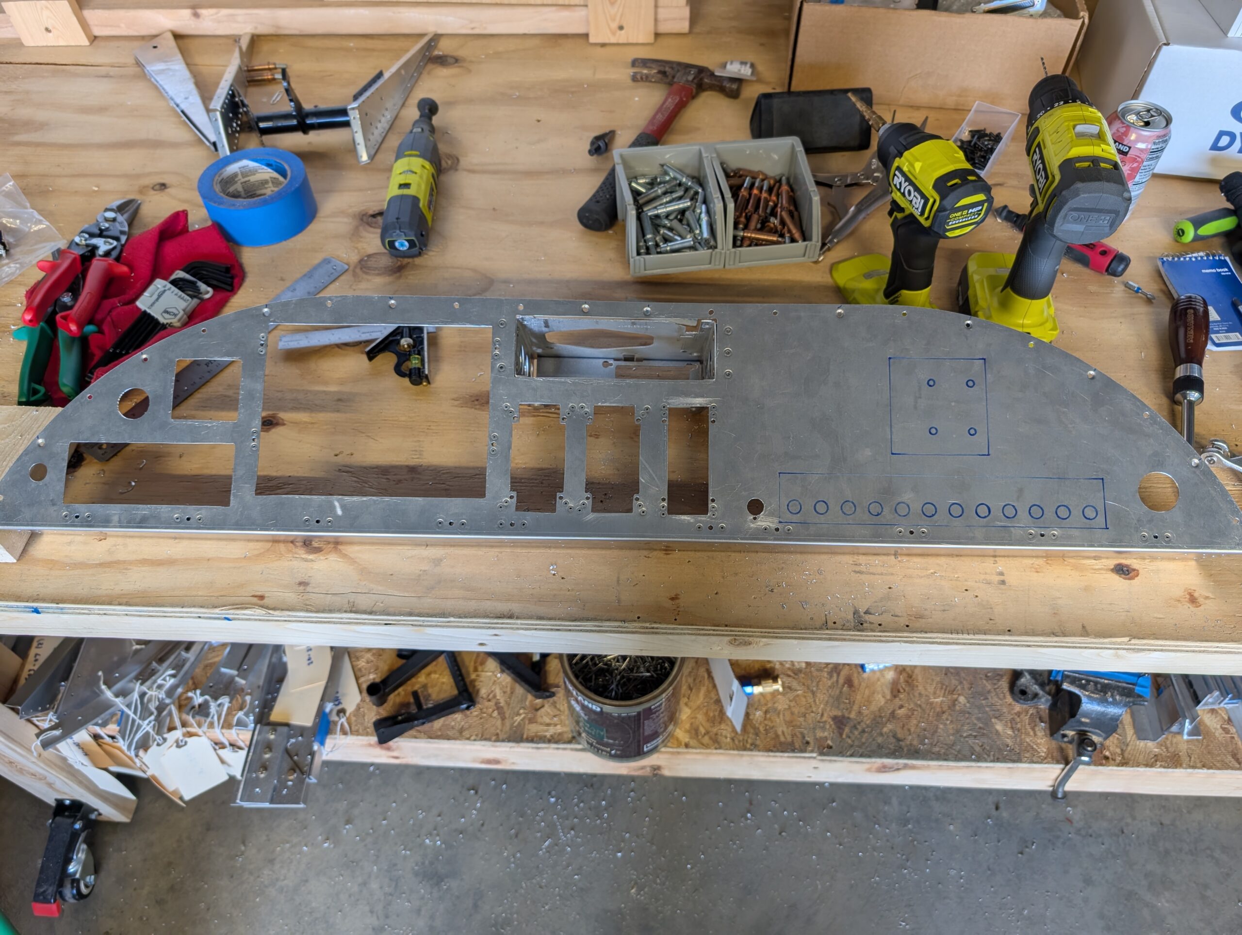
Continued cutting out holes for instruments in panel backer. Test fit with components part-way through cutting. Began prepping GPS175 tray for installation by cutting out side brackets from .063 sheet. Bent brackets and drilled lighting holes. Cut out notch in LH bracket for SkyView display nutplate. Hours Worked: 3.72
Panel Installation – Part 3
Continued locating and installing nutplates into panel blank. Marked access hole locations on RH side of panel blank. Marked hole centers and began cutting out instrument holes into panel backer. Hours Worked: 2.57
Follow-up Storage Treatment #3
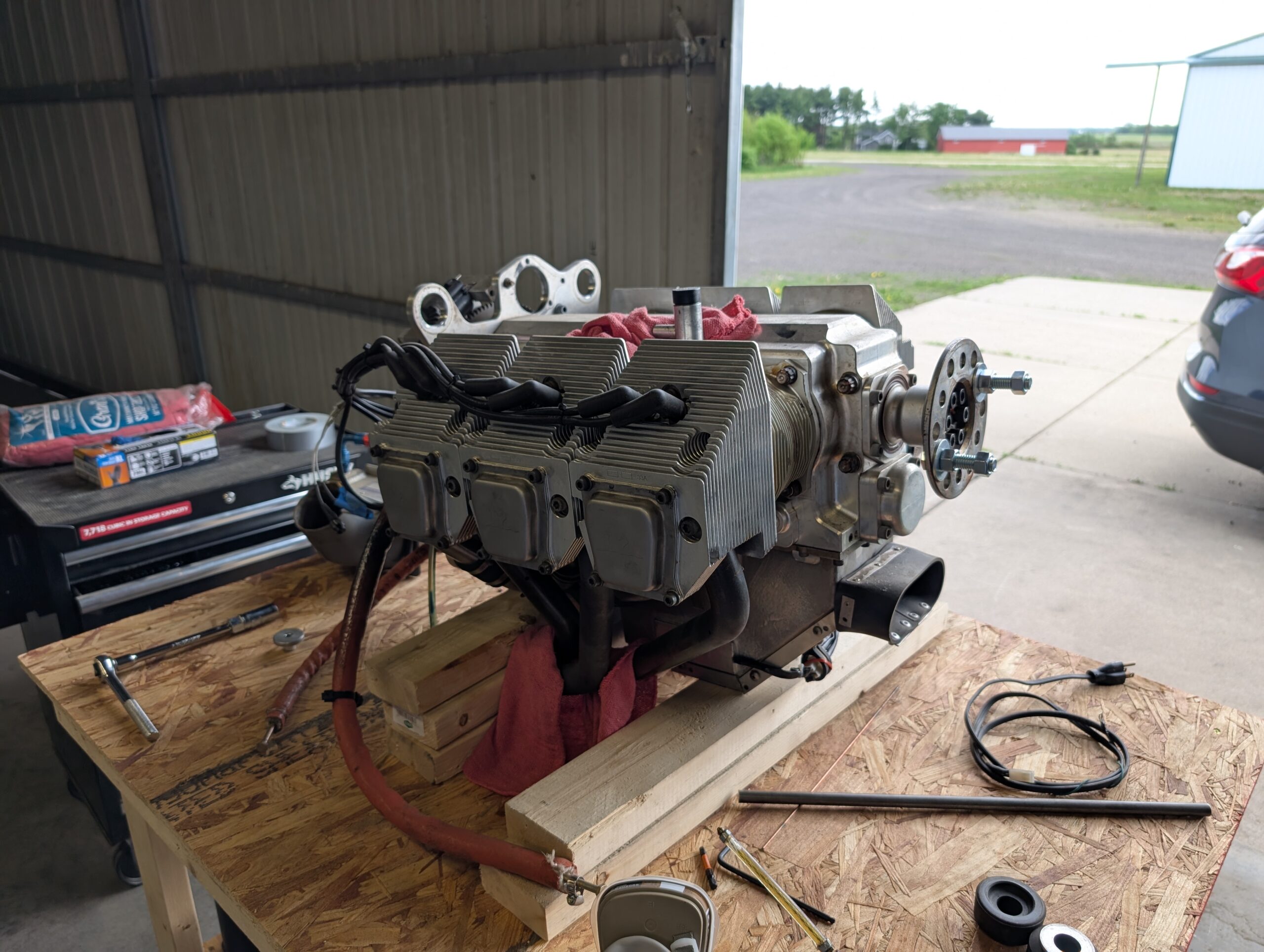
Performed long-term storage procedure IAW Jabiru Maintenance Manual. Removed plugs and lubricated cylinders with Phillips 20W50 Anti-Rust Oil. Reinstalled plugs but did not torque. Removed rocker covers and lubricated rocker chambers with same oil. Reinstalled rocker covers but did not torque. Pulled prop through 15 times. Hours Worked: 0.63
Panel Installation – Part 2
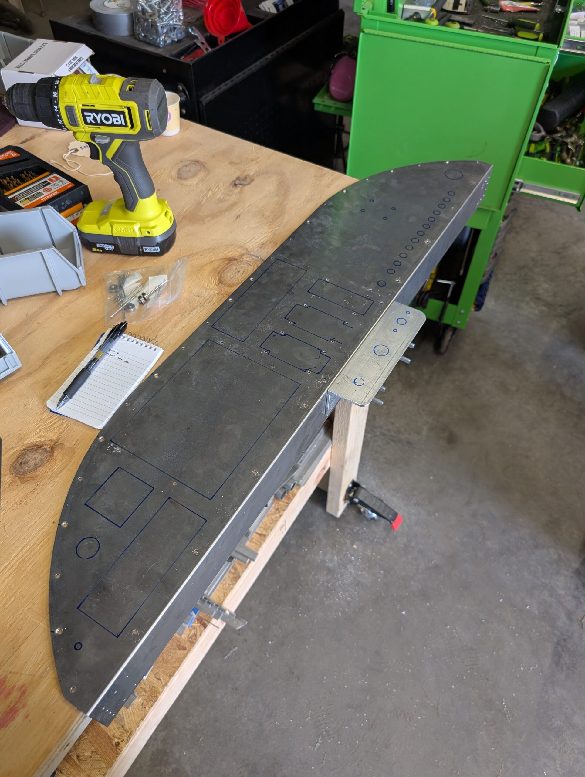
Continued prepping panel flange by dimpling right side flange and installing nut plates. Installed flanges back onto glareshield and checked fitment with panel and panel covers. Removed panel and covers and marked hole and cutout locations on panel. Cut a piece of aluminum angle scrap to fit in throttle/mixture area behind panel cover and below…
Panel Installation – Part 1
Began prepping panel for final riveting and installation by mocking up panel covers on panel backer. Fitment was just a little tight so filed away some material from inside edges of panel covers. Removed panel and flanges and dimpled every other hole for flush CCC rivets. Began installing nut plates in other holes on panel…
Elevator Horn Re-do – Part 1
After some reflection on the slight shortcoming of up elevator travel, it was decided that the elevator horn should be removed and repositioned slightly forward to enable more up-travel. While the existing elevator horn will be retained the inboard elevator ribs will be removed and replaces so that the horn can be located more forward…
Tail Installation – Part 3
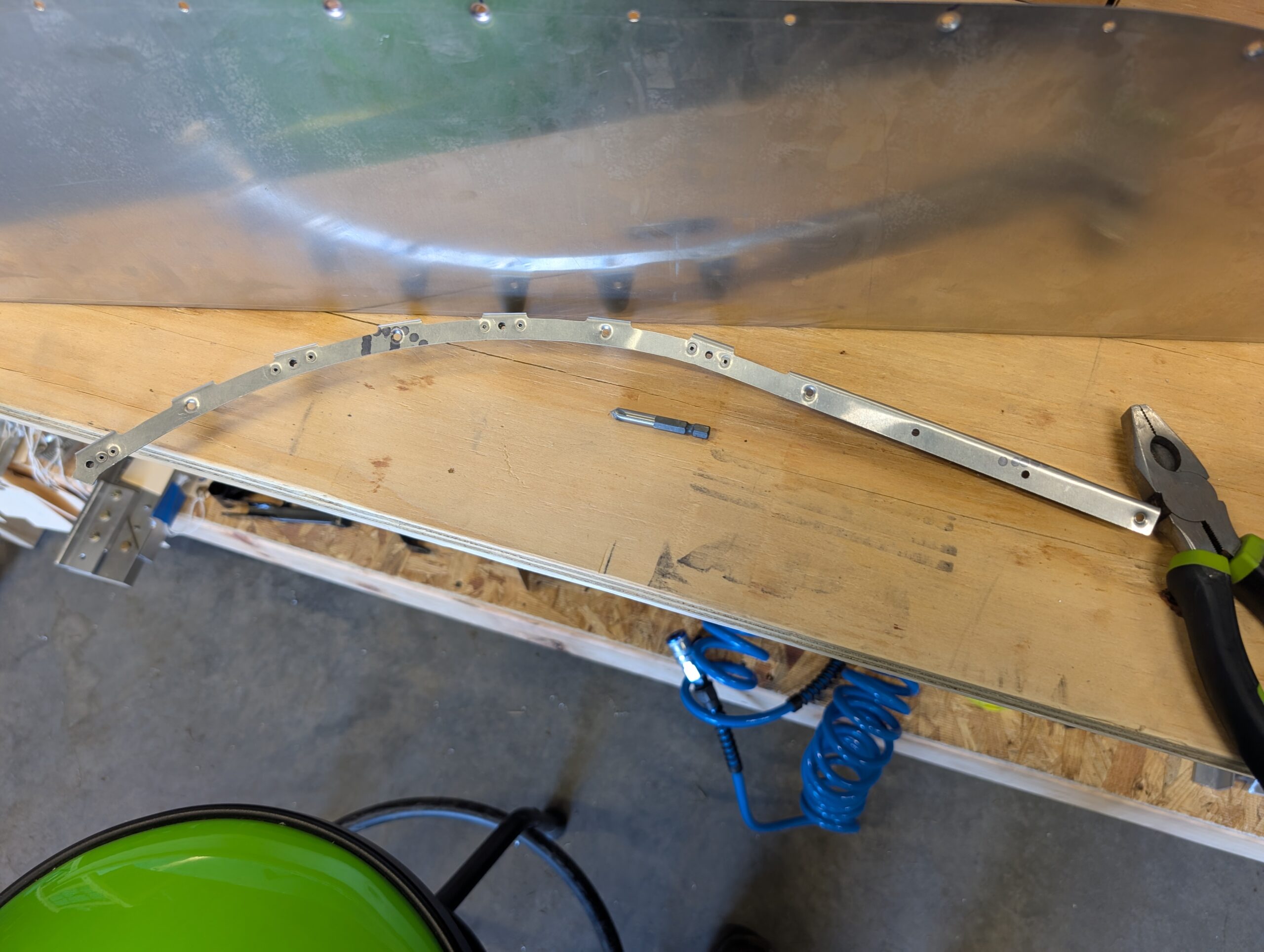
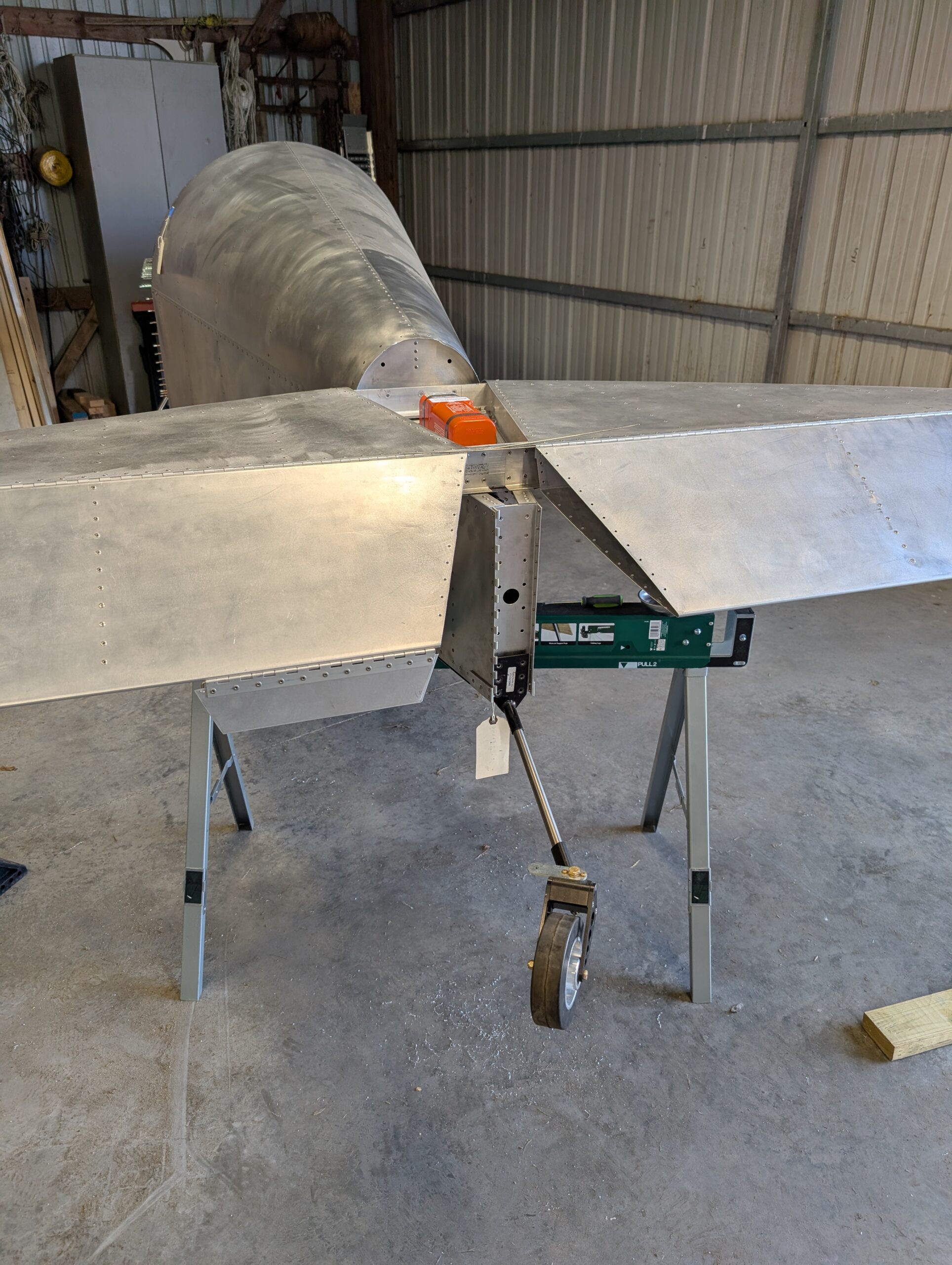
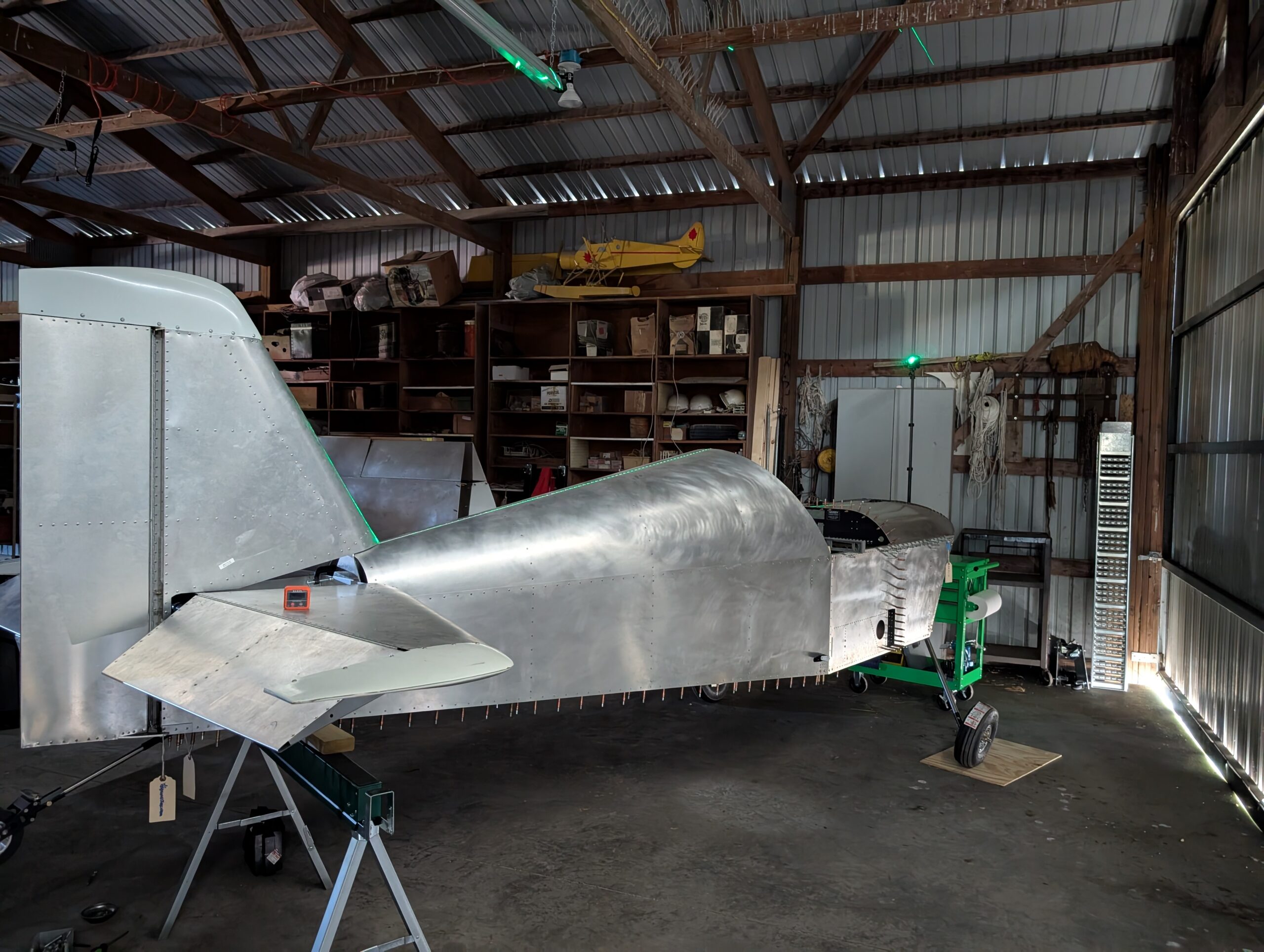
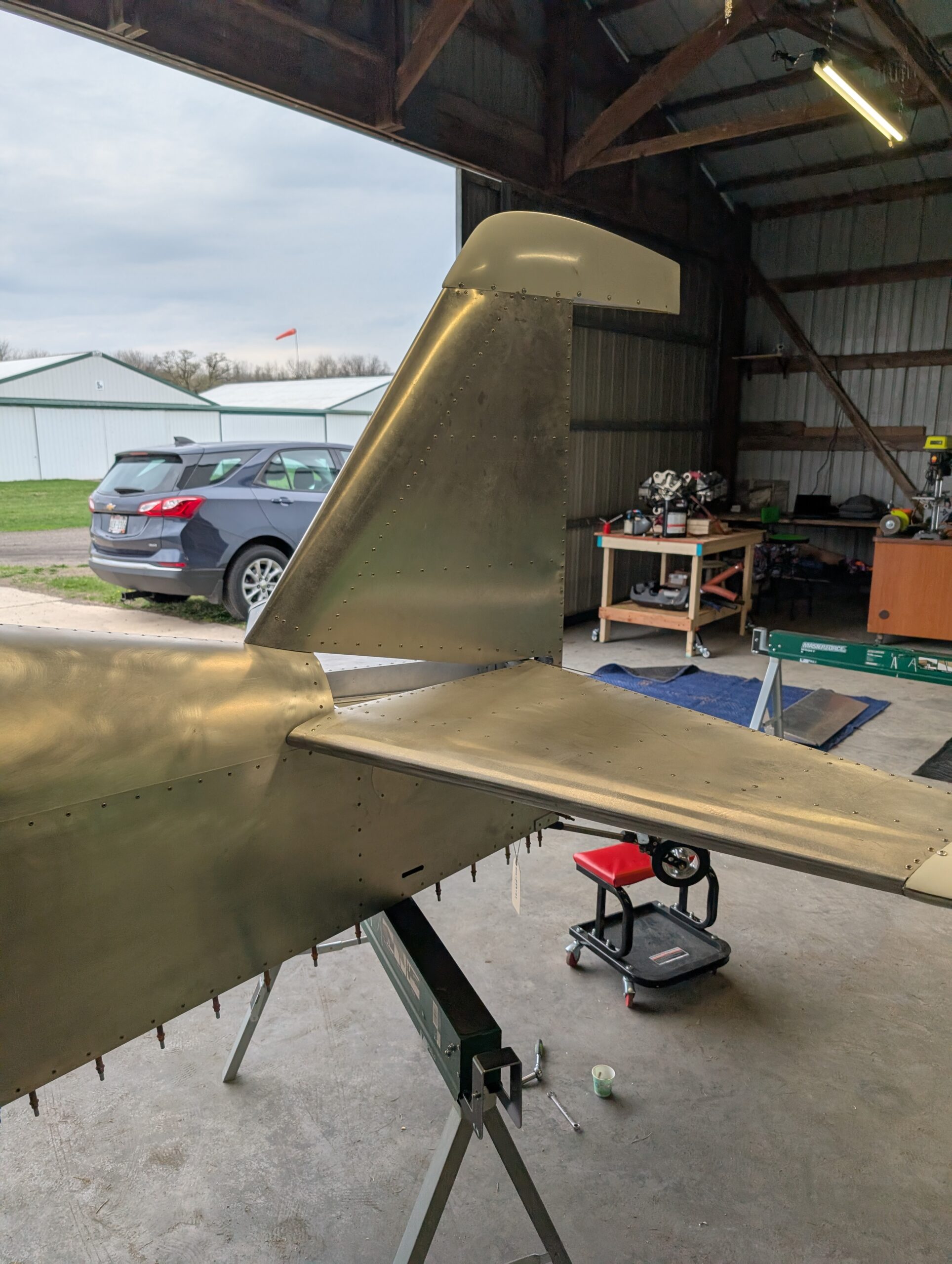
Mocked up ELT location on rear shear web and marked vertical stabilizer on where skin needs to be trimmed. Removed vertical stabilizer and marked out mounting hole location on shear web. Trimmed vertical stabilizer skin and riveted ELT mount and clamps to fuselage. Painted elevator horn with spray paint. Reattached vertical stabilizer with AN3 and…
Tail Installation – Part 2
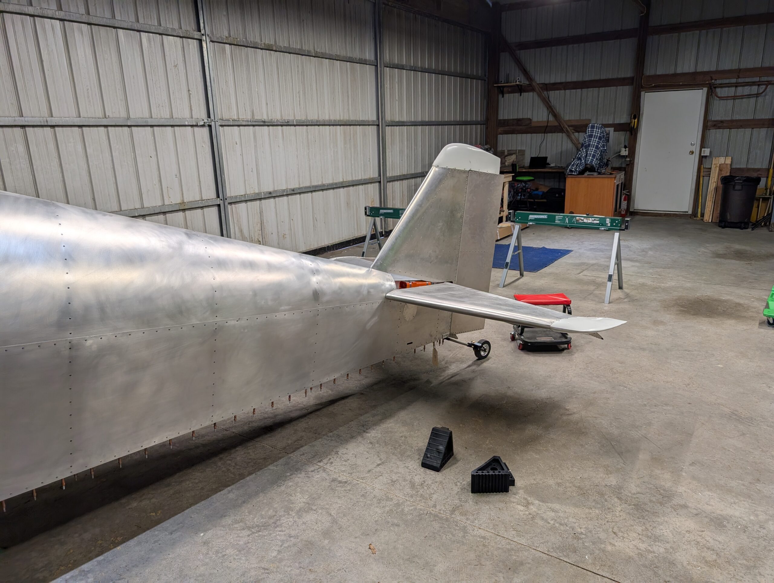
Mocked up vertical stabilizer into place and noticed elevator horn was impacting vertical stabilizer skin and preventing full motion. Removed vertical stabilizer and trimmed skin at base. Continued to file elevator horn to ensure full 25 degrees of pitch up. Inserted elevator pushrod into fuselage before getting too far. Set elevator hinge pins all the…
Tail Installation – Part 1
Began tail surface installation by moving tail surfaces from house to hangar. Discovered that horizontal stabilizer skins were installed upside down and that the bottom skins would need to be trimmed to fit around fuselage tail cone. Using the top side skin as a reference, trimmed bottom skin to clear fuselage tail cone. Will need…

Panel Redesign – Part 5
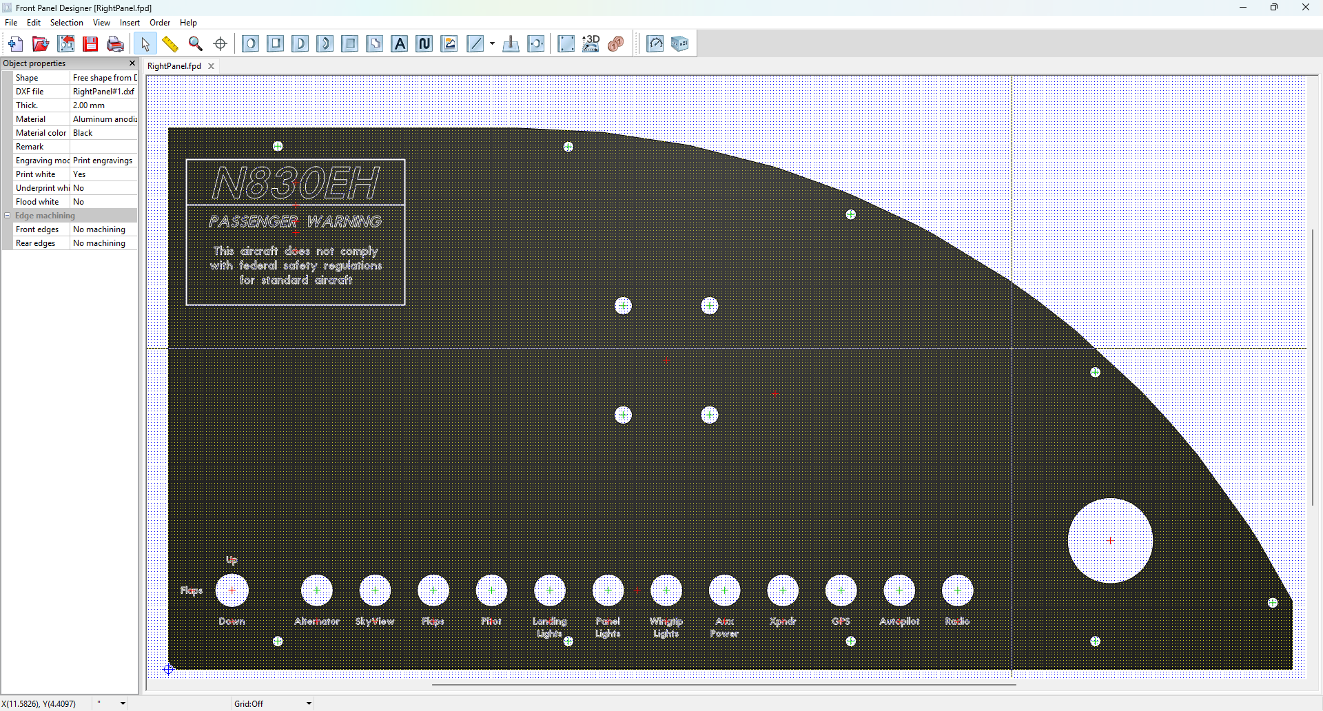
Exported panel files in Solid Works to DXF format to upload into Front Panel Designer. Imported files and began placing text on panels. Used Futura font and 10pt size in most places. Printed out front panel designs full scale and taped to a cardboard mockup for test fitting once more panel components arrive. Hours Worked:…
Control Pushrod Assemblies
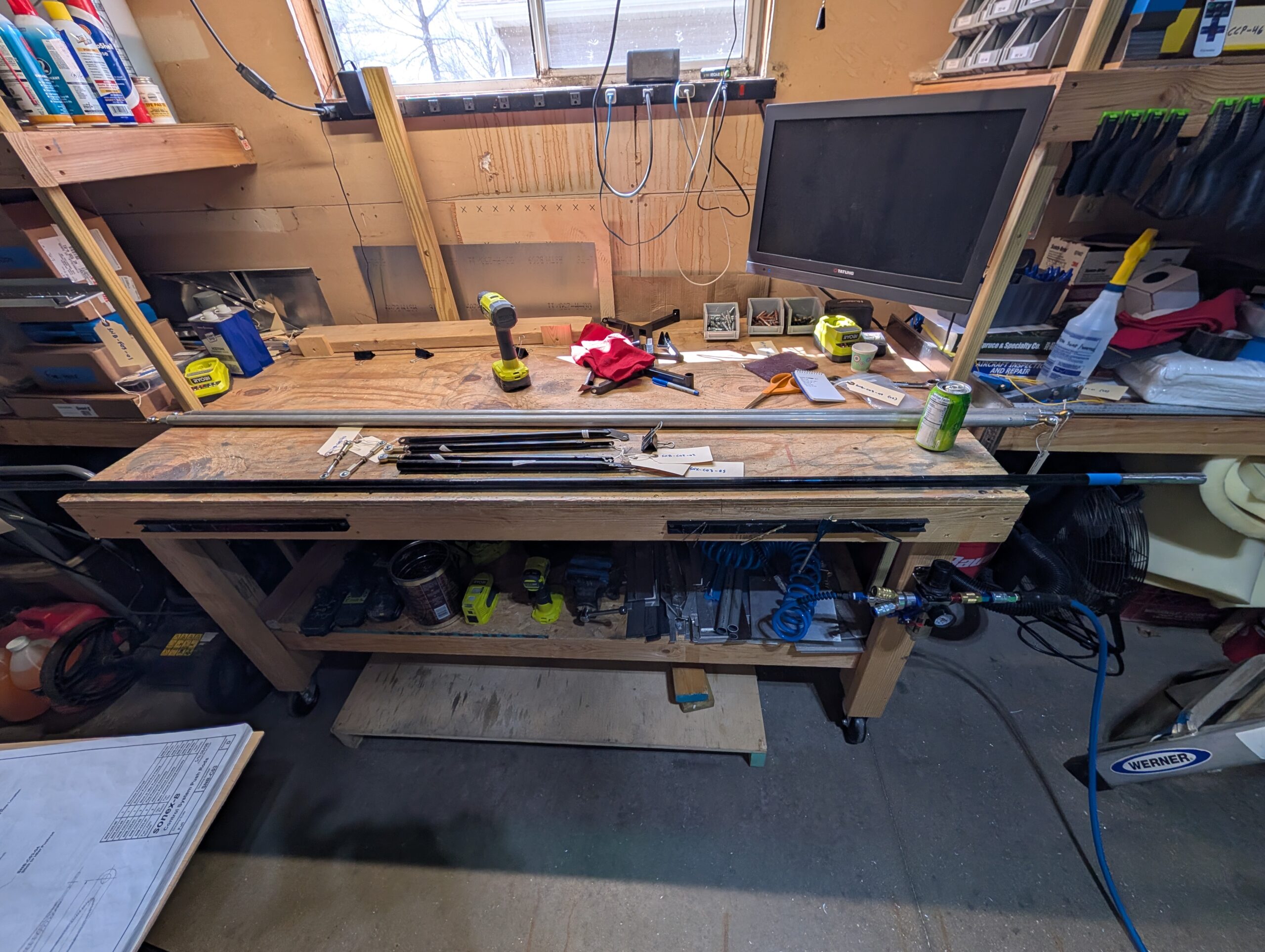
Cut aileron tube stock to size per plans for dual-stick configuration. Marked and drilled holes for pushrod end fittings, then deburred and riveted -01 main aileron pushrod assemblies. Pressed spoiler bearings into rod end bearings using vice then installed onto main pushrod with jam nuts using dimensions given in plans. Drilled witness holes into female…