emkrueger830

FWF Wiring – Part 3
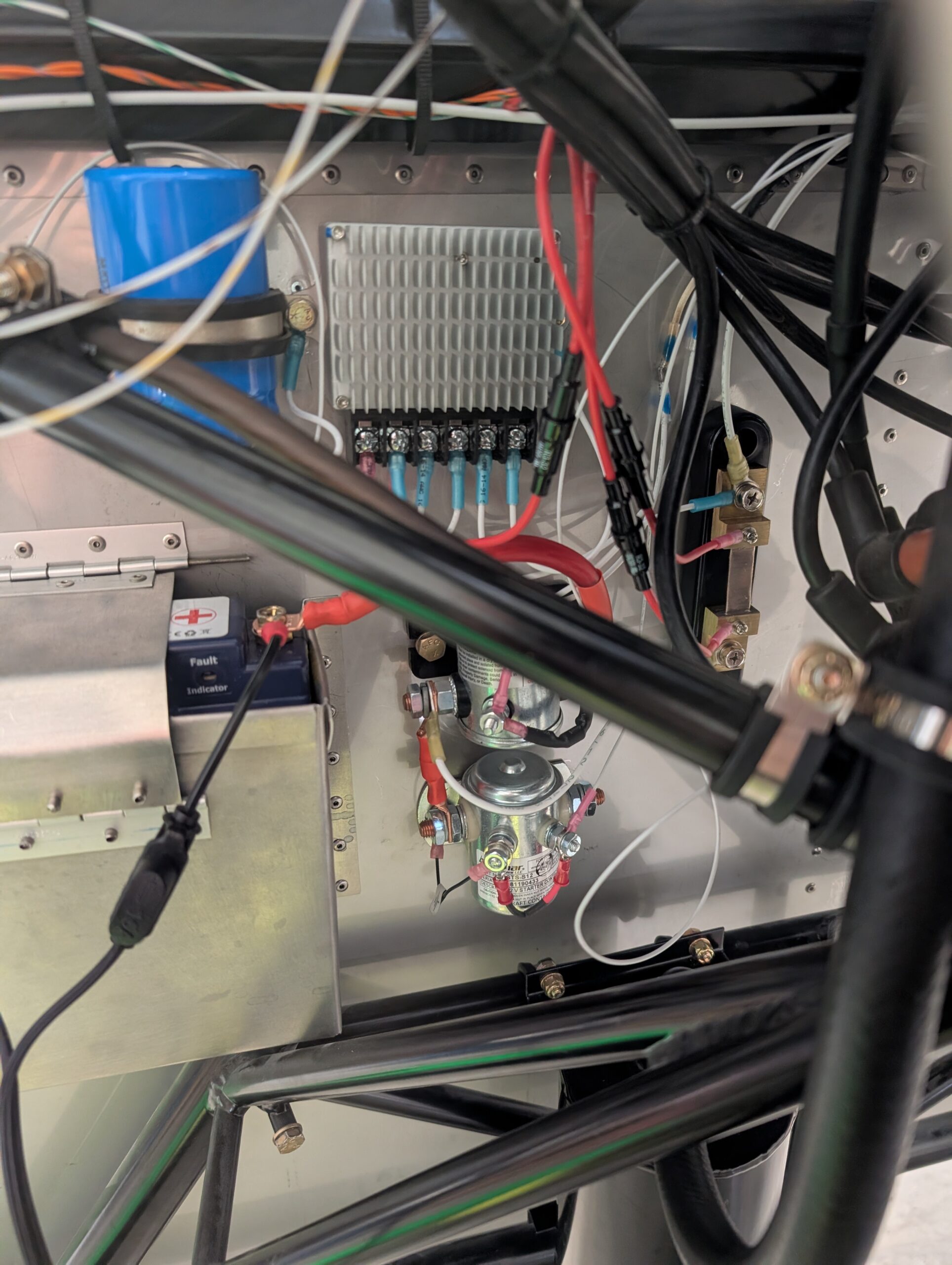
Terminated amp shunt wires and tachometer lead by installing inline fuse holders with 1 amp fuses. Ran voltage regulator reset line from panel to voltage regulator. Hours Worked: 0.89

Oil Cooler and Separator Installation
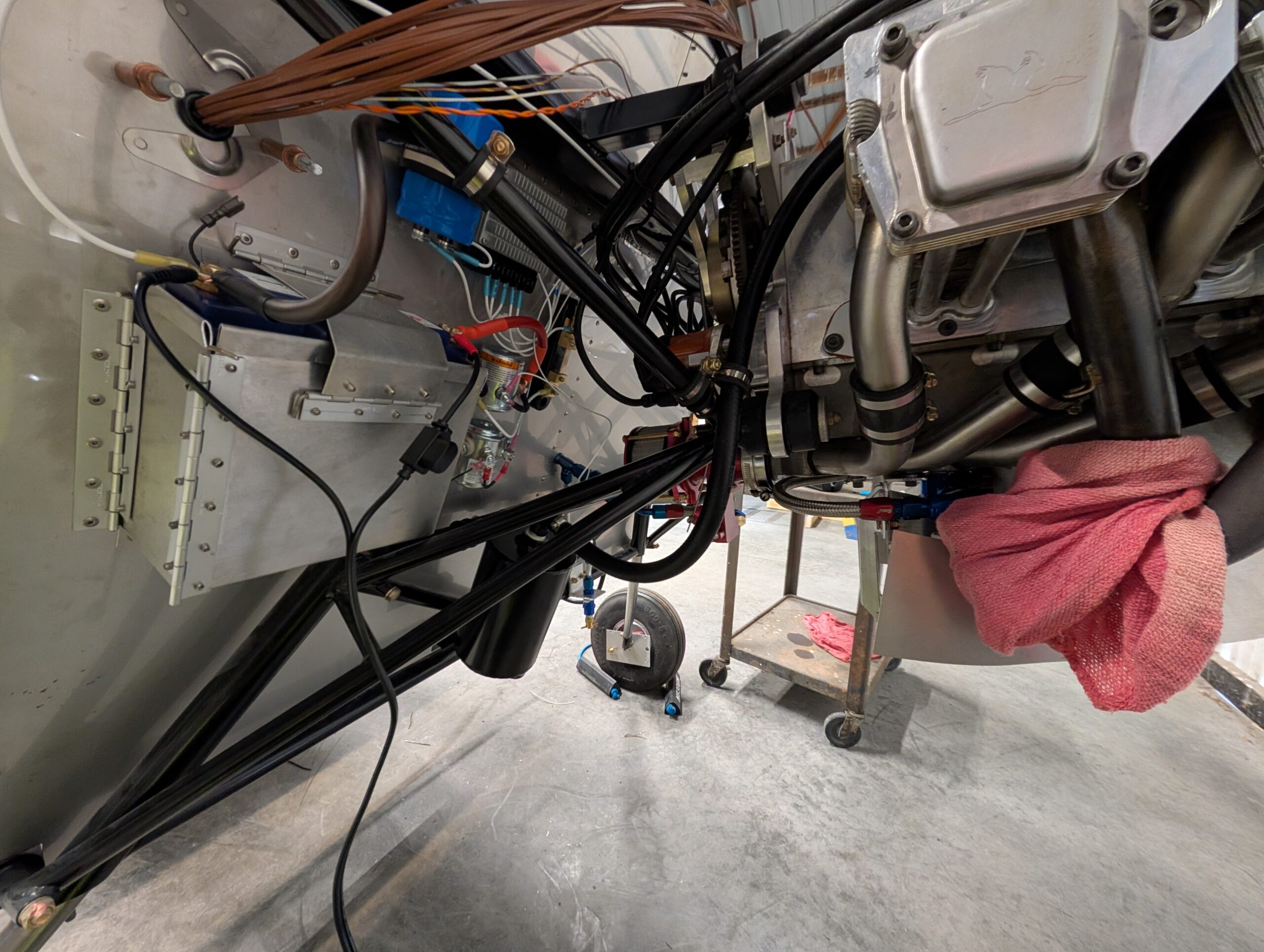
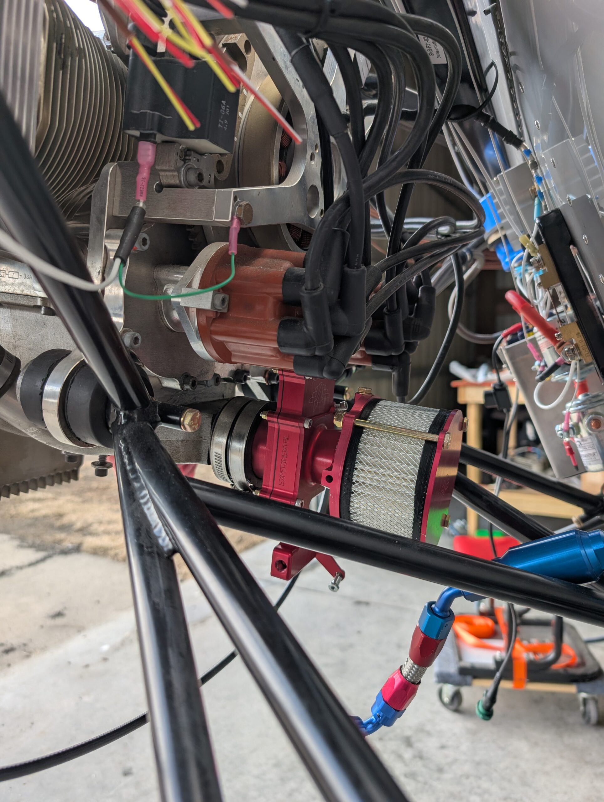
Mounted oil cooler bracket onto bottom side of intake and secured bolts with Loctite 242. Temporarily mounted oil cooler to engine then marked areas of baffling to remove for block heater and oil drain. Installed AN fittings into top of oil cooler. Made oil cooler hoses and routed them from oil filter housing to oil…
GPS Antenna Install
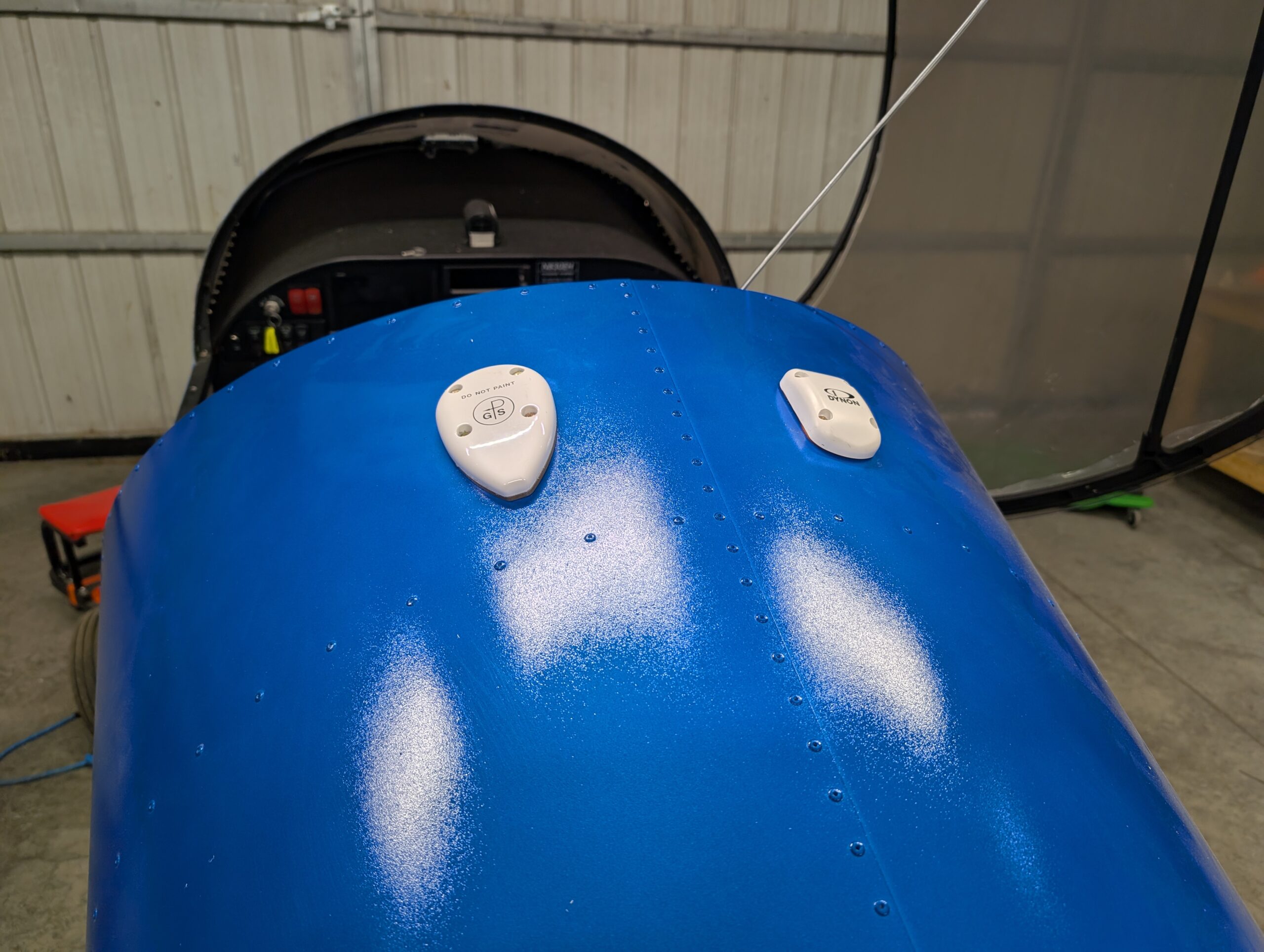
Drilled mounting holes for both GPS units on top of turtle deck and installed antennas using MS24693 screws. Applied clear silicone sealant around edges of GA 35 antenna to prevent water intrusion into baggage compartment; did not use sealant under Dynon antenna because a gasket was included. Secured wiring for SV-GPS-250 antenna. Hours Worked: 0.83
Mixture Cable Install
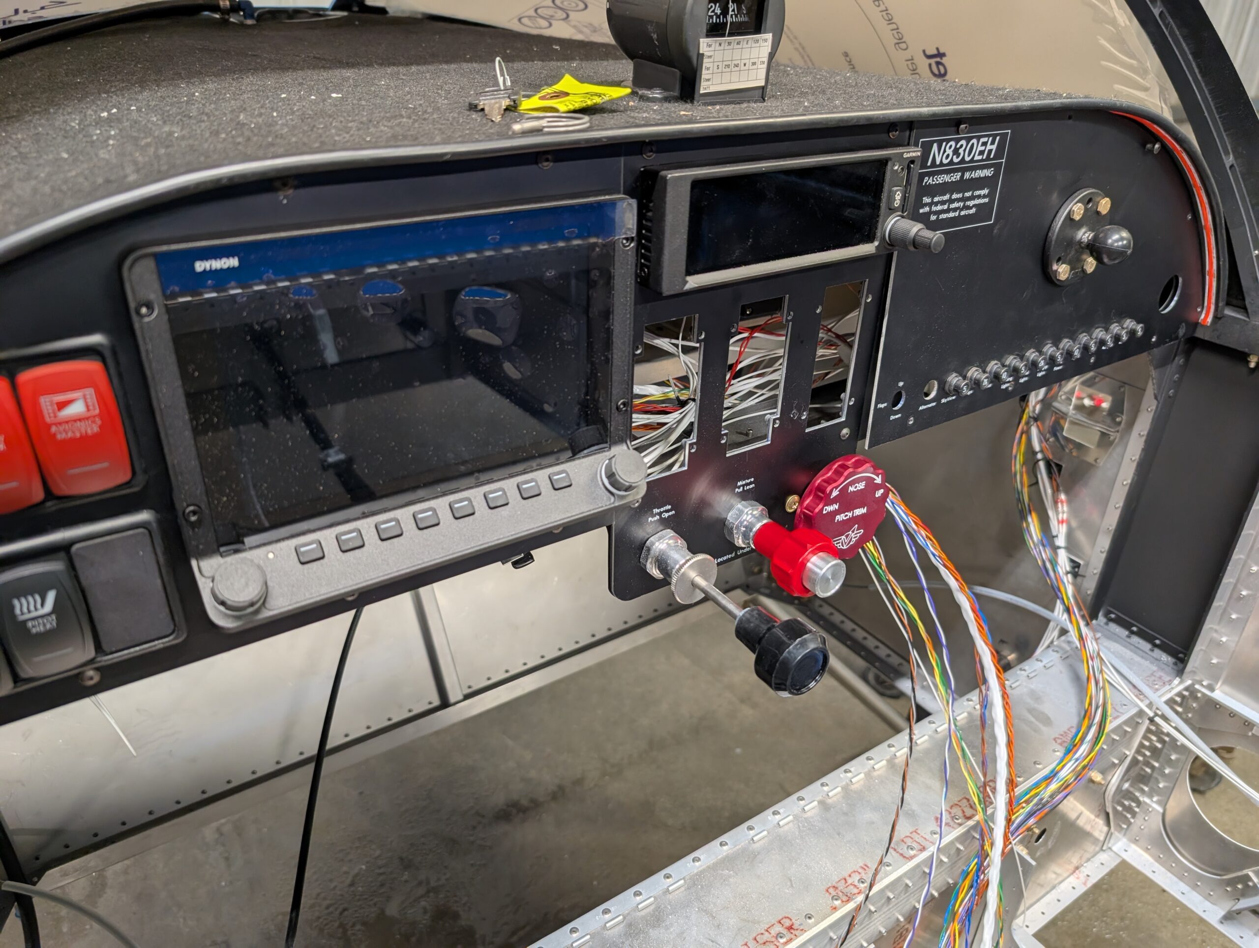
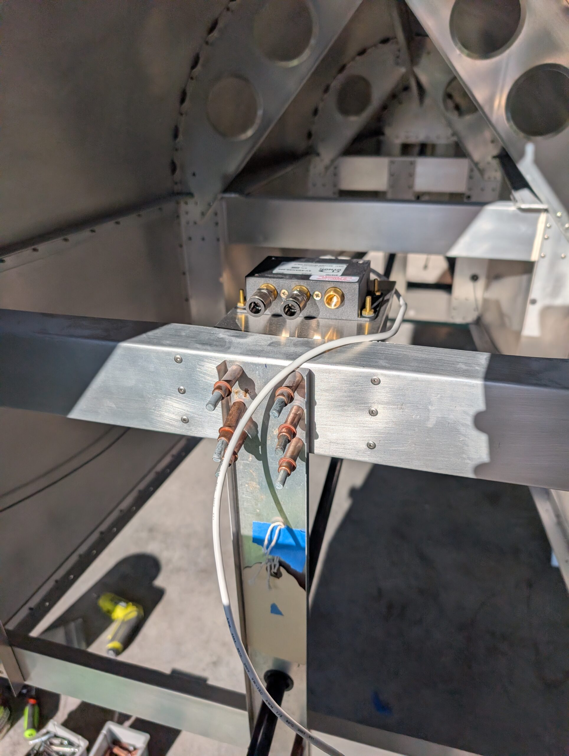
Installed mixture cable into center panel section and routed cable through previously installed cable safe. Measured out approximate length and removed inner cable from jacket (making sure to carefully catch ball in cable mechanism). Trimmed outer jacket then upsized cable hole in AeroInjector to 1/4″. Installed AeroInjector back onto back side of motor and ran…
Garmin GPS 175 Install
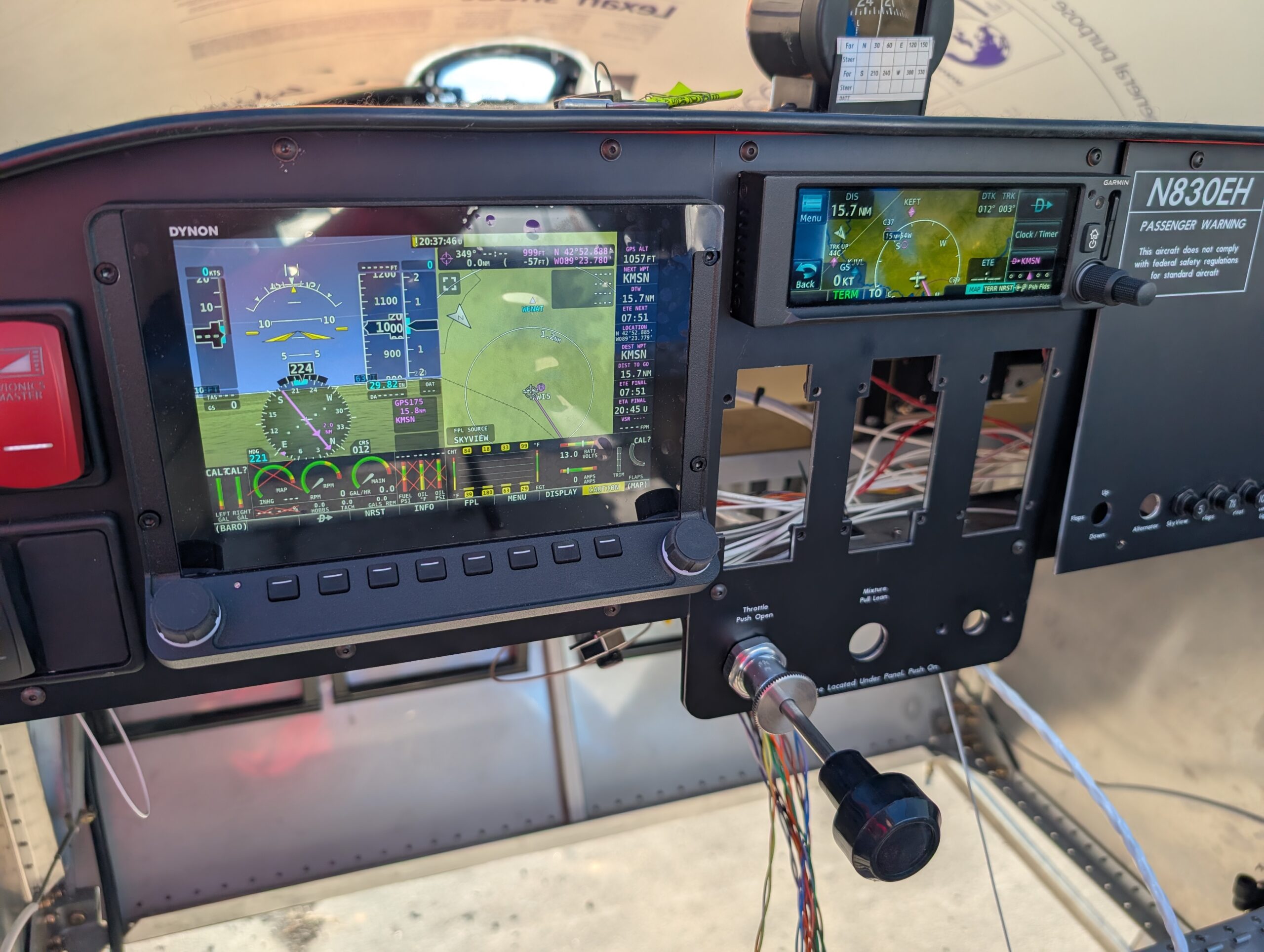
Diagnosed GPS175 screen issue by dissassembling unit and cleaning and reseating screen ribbon connectors; ops check good. Installed GPS harness onto back of tray and wired up ground and power connections. Installed unit and tested; ops check good. Fabricated antenna cable from RG400 coax and drilled center holes for both Dynon and Garmin GPS antennas.…
GPS 175 Harness Wiring
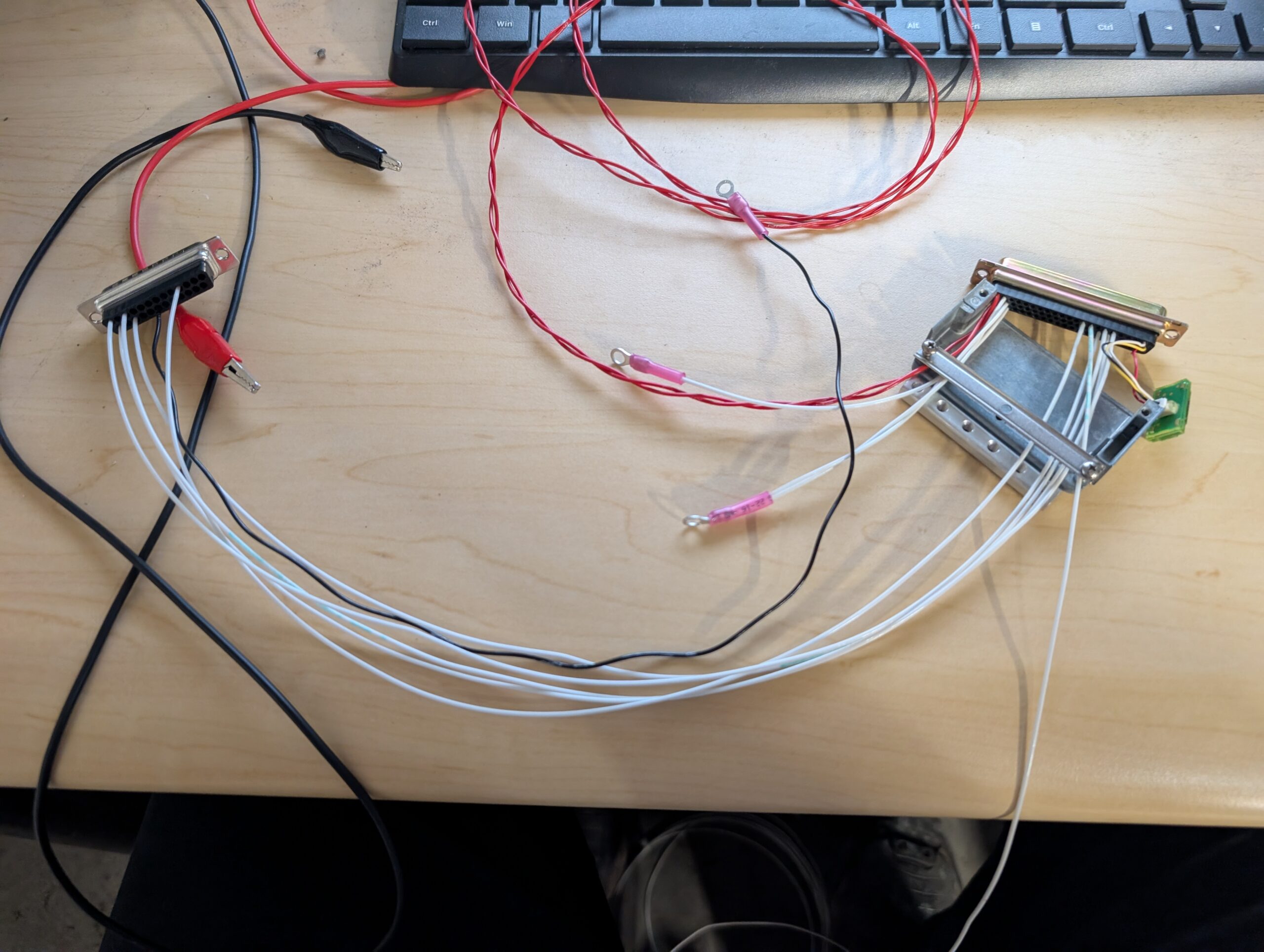
Created Garmin GPS 175 and Dynon SV-ARINC-429 harness by cutting wires to length and installing high density Garmin pins on one side and standard density D-sub pins on the other end. Referenced the wiring diagram and Dynon’s 3rd party connection guide to fabricate harness. Opted to use common rail on the Garmin connector for ARINC…
AHRS Unit Shelf
Installed GPS 175 tray behind panel in preparation for GPS install. Connected SkyView WiFi adapter to back of display along with USB extension (which will be secured at a later time). Fabricated shelf for SV-ADAHRS-200 box from 0.032 sheet. Bent and cut flat template then clecoed onto back side of the #2 cross tie. Checked…
Throttle Bell Crank – Part 2
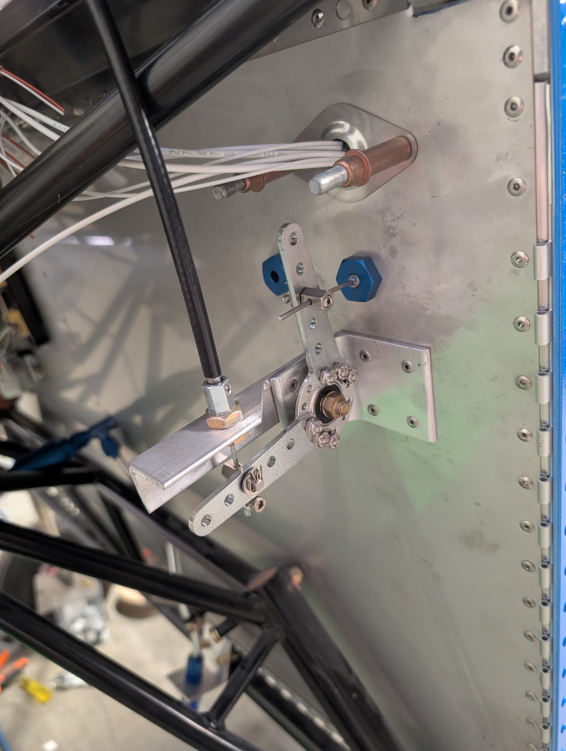
Installed throttle cable in center panel area. Located throttle and mixture cable pass-through locations on firewall and prepared holes for cable bulkheads. Installed both cable safes. Located throttle bellcrank assembly based on throttle cable pass through then transferred mounting holes onto firewall. Cleaned up bellcrank assembly then riveted pieces together and to firewall. Tested cable…
Fuel System Electronics Wiring
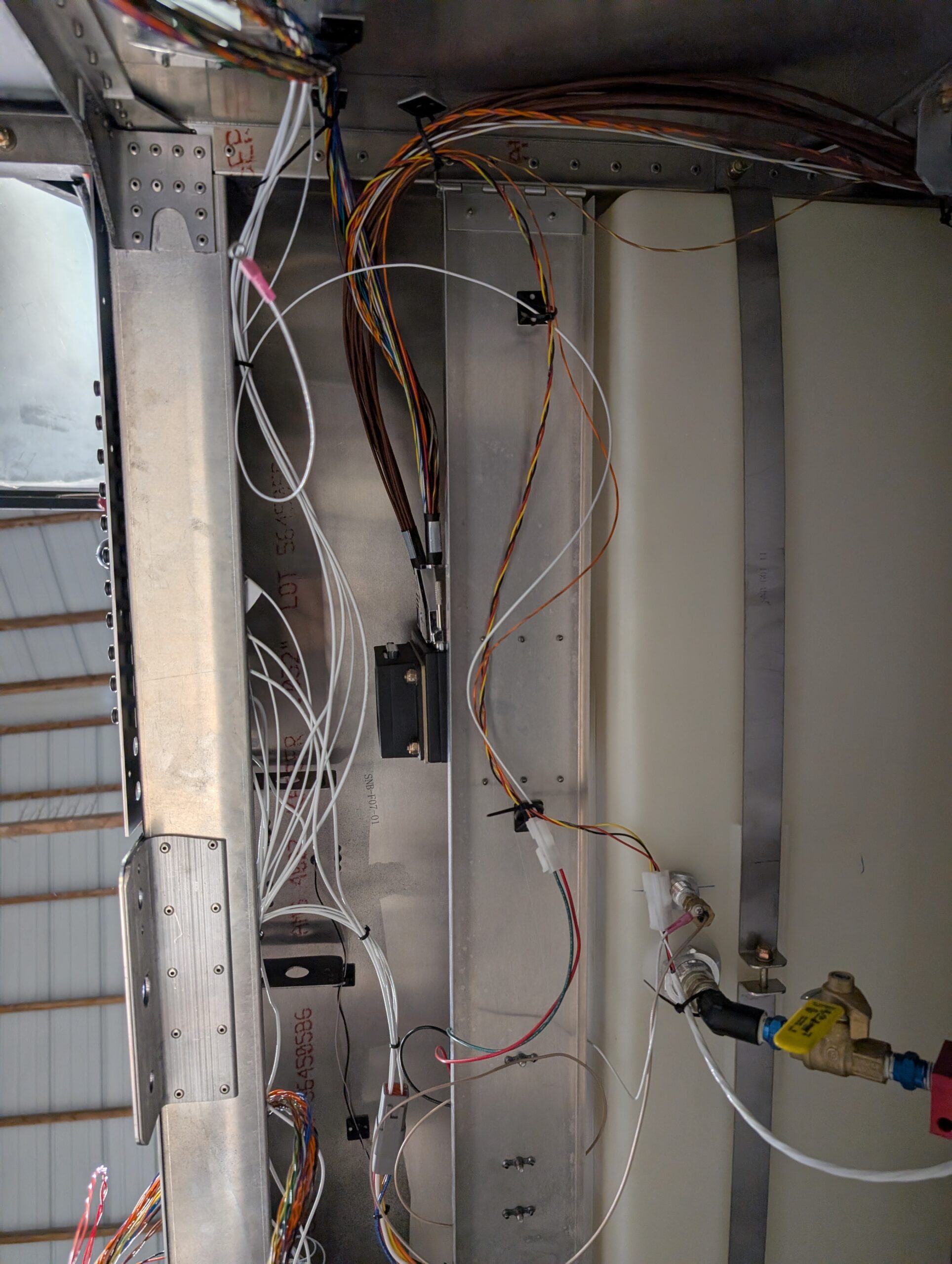
Installed molex connectors on fuel probe and fuel flow transducer and connected components to EMS harness and SkyView circuit breaker. Attached voltmeter input of EMS box to main bus bar. Ran firewall forward wires of EMS harness through gromet to engine compartment. Installed main display harness and hooked up power and ground connections. Connected SV-EMS-220…
Throttle Bell Crank – Part 1
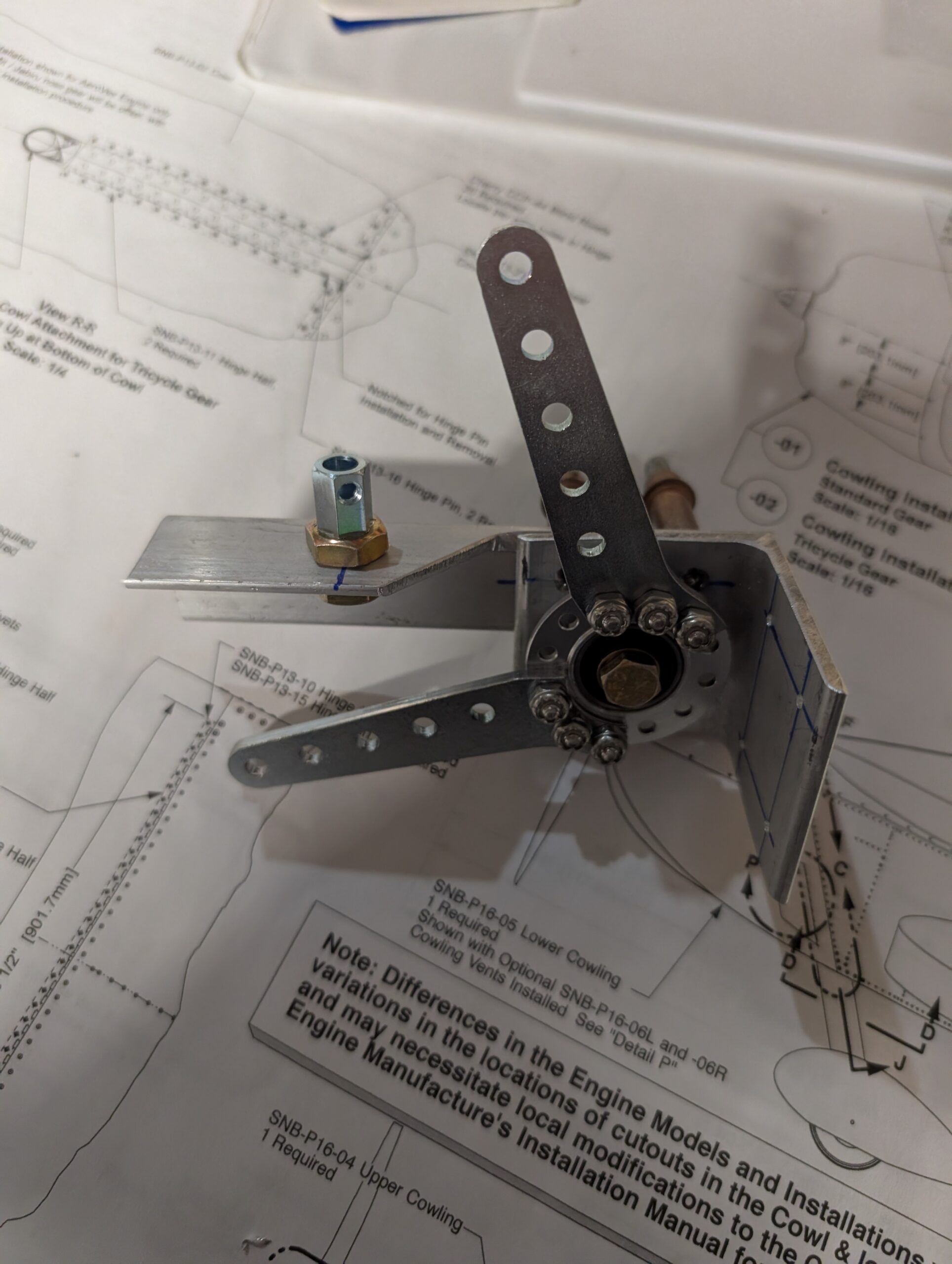
Because we are planning to use a traditional push-pull throttle (instead of a Sonex throttle quadrant) with the AeroInjector, we needed a way to reverse the throttle direction. Assembled throttle bell crank and created mounting bracket from scrap 2″ and 1″ aluminum angle. Cannibalized cable parts from spare Sonex throttle components. Will need to final…
Engine Installation – Part 1
Continued working on Sonex FWF manual for the Jabiru by marking and trimming cooling fins on cylinder #1. In lieu of further trimming cylinder fins to fit spark plug CHT ring sensors, will opt to use #8 ring terminal sensors for easier access. Removed existing baffling from front of engine and old oil cooler. Measured…
Thrust Line Measurement
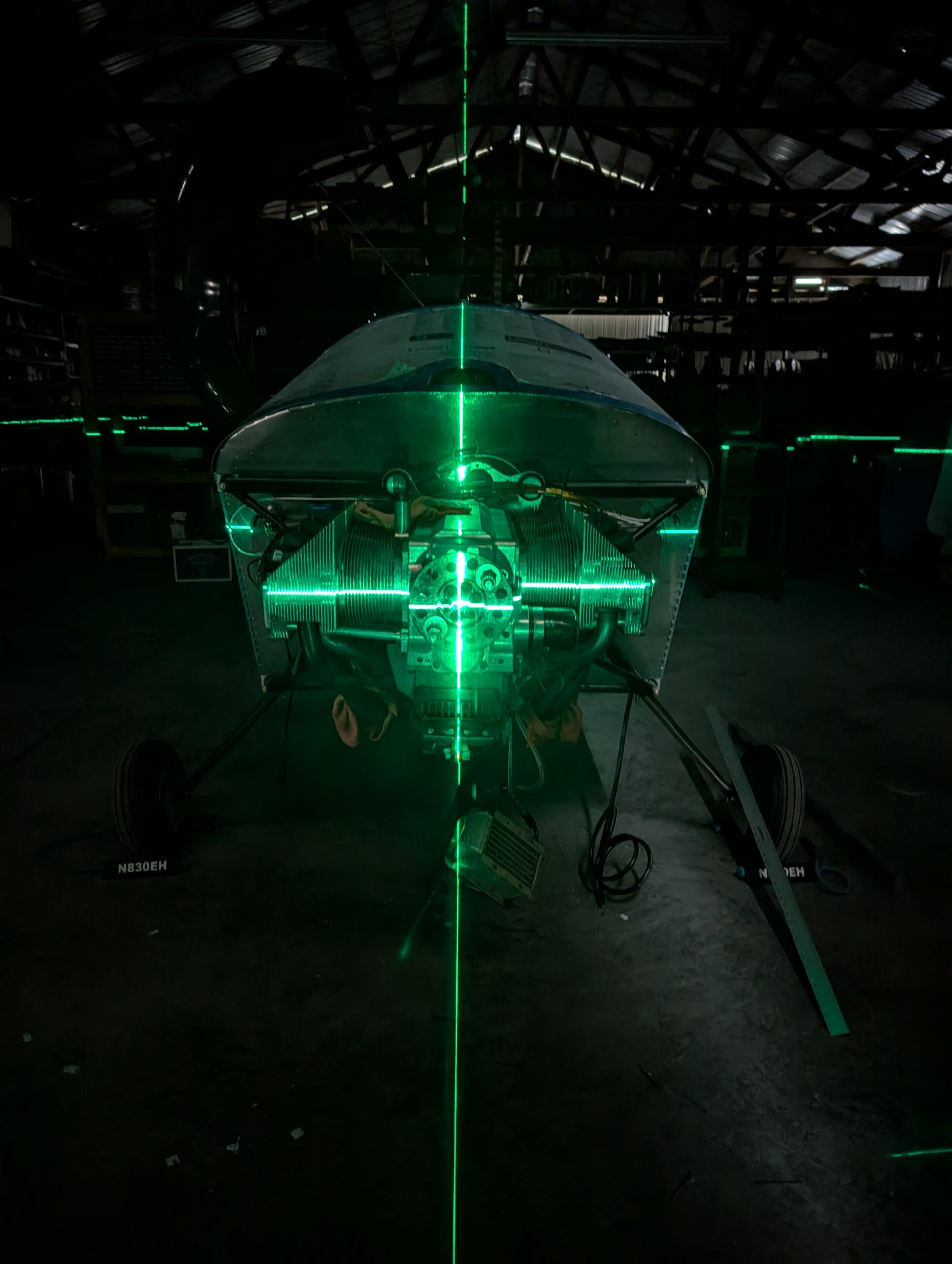
Verified engine alignment before moving forward by leveling fuselage with saw horse under tail and setting up laser level though center of crank. Measured bottom front corner of fuselage at 22.75″ from floor and center of crank as 40.25″ from floor leaving 17.5″ from thrust line to bottom of fuselage; right on spec.