emkrueger830

Cowl Fitment – Part 4
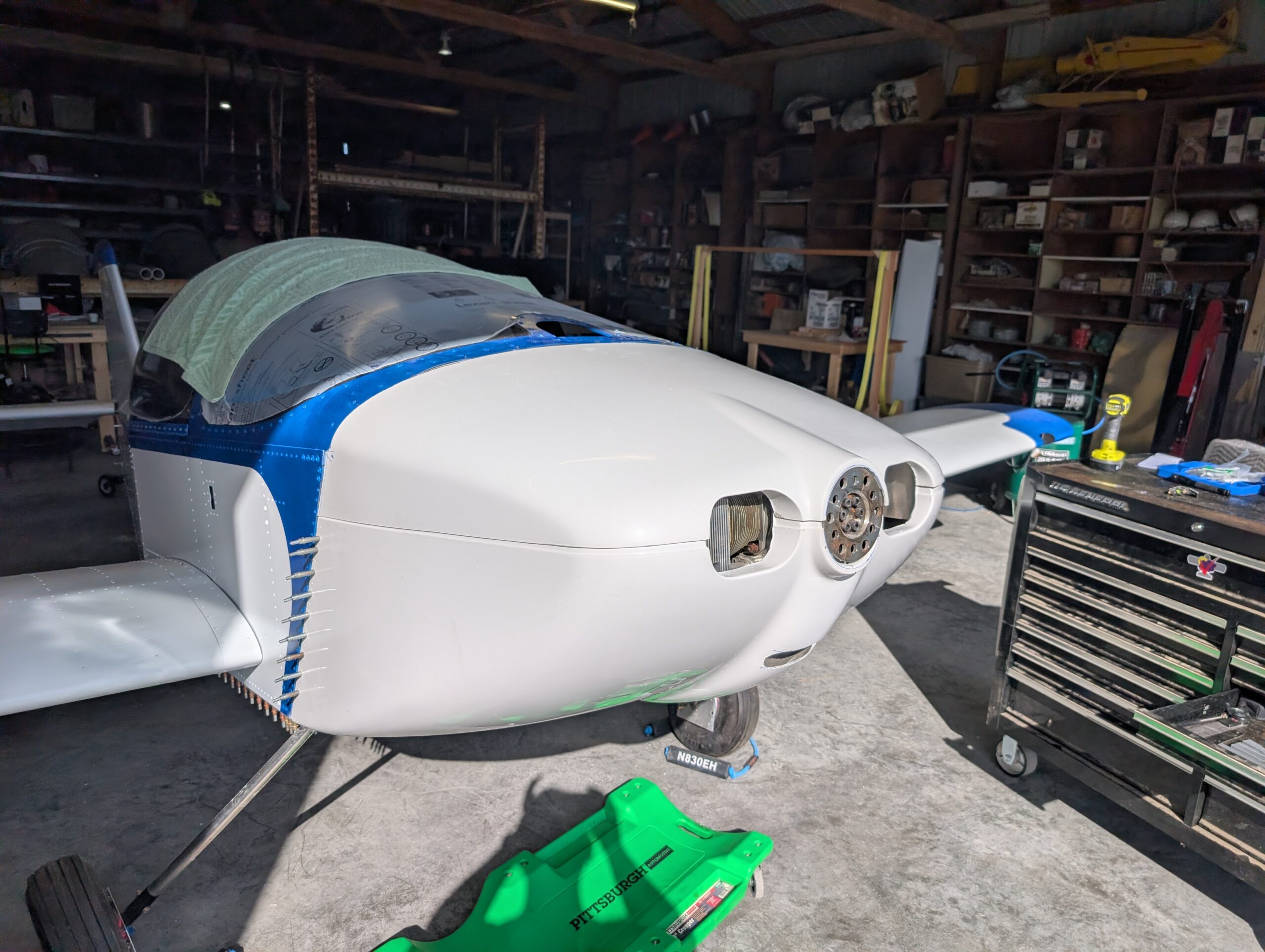
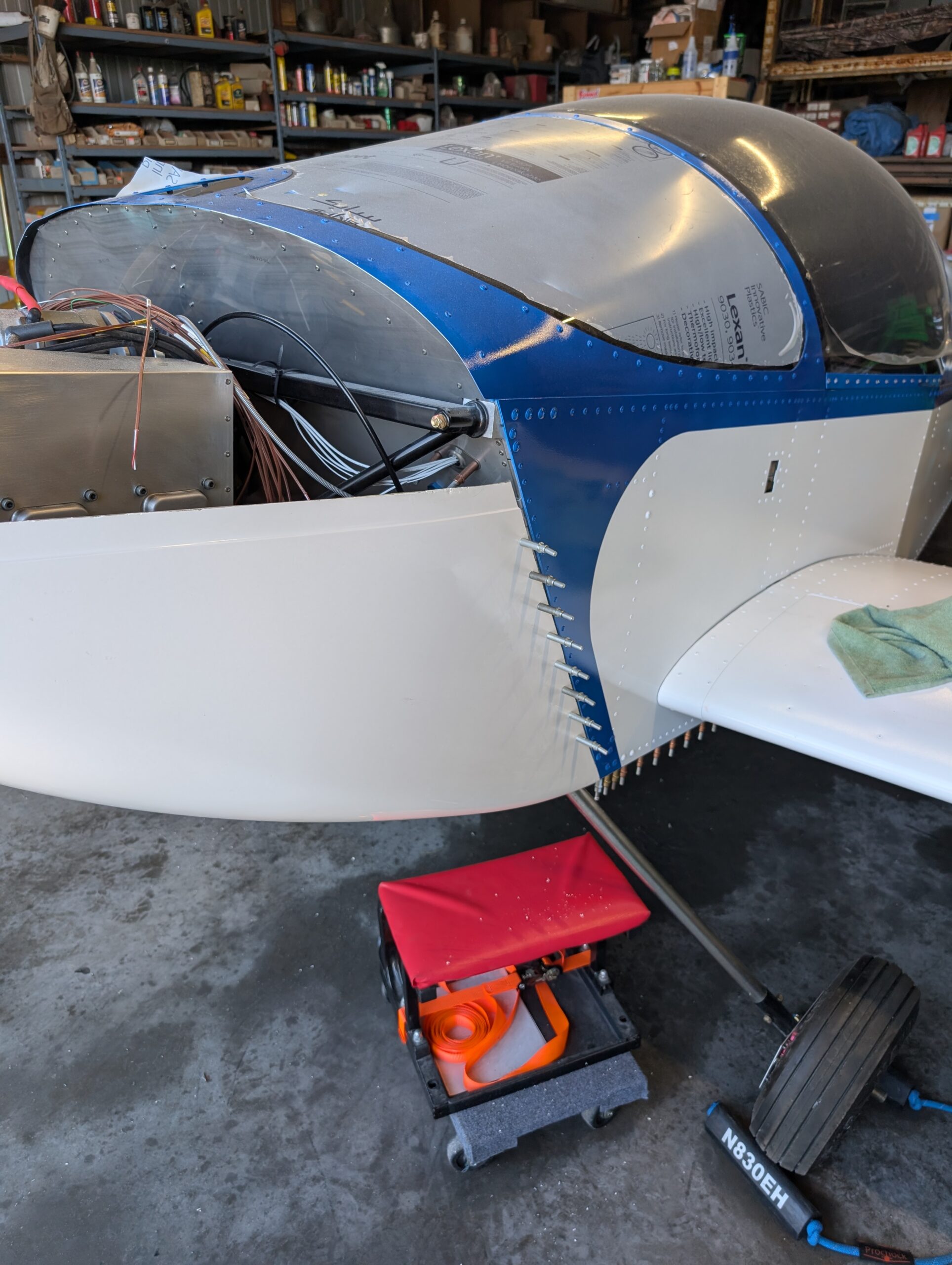
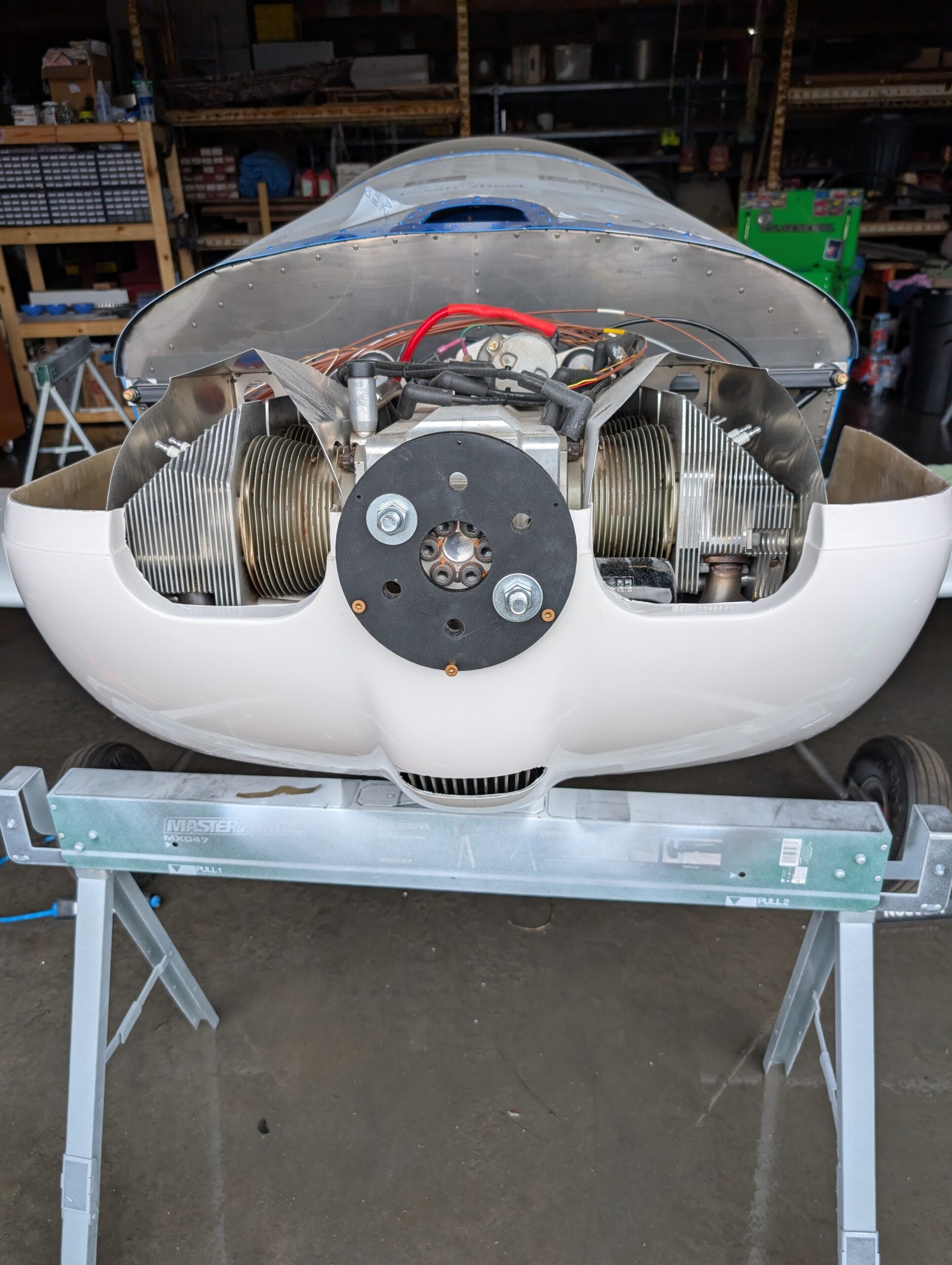
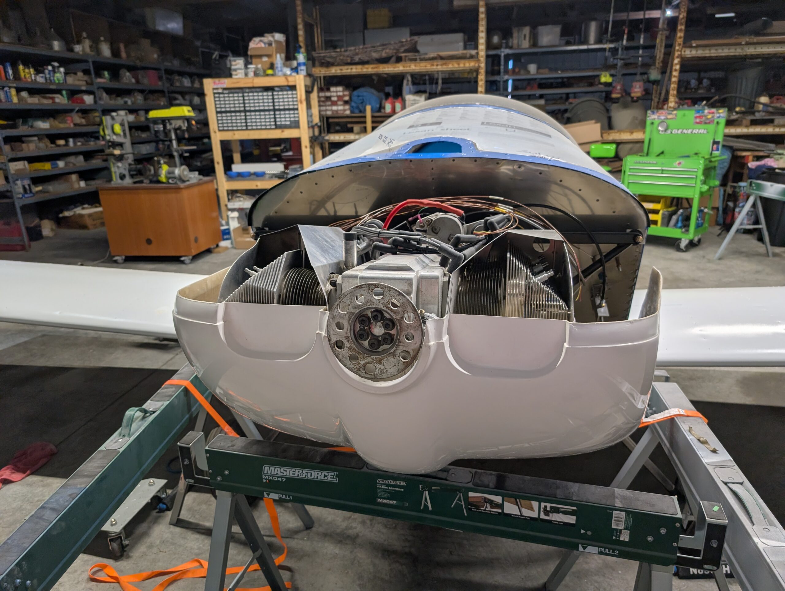
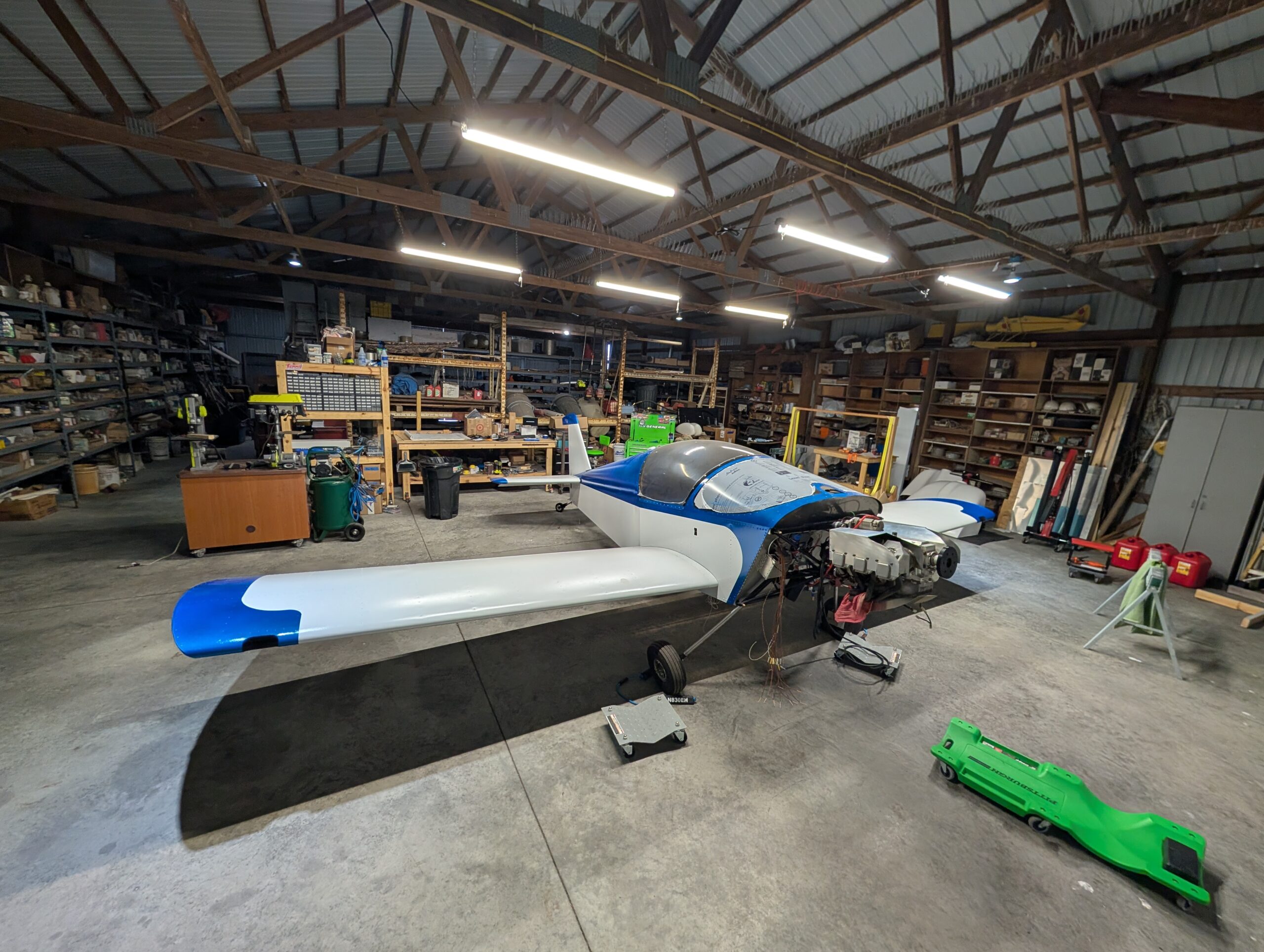
Began fitting upper cowl by placing onto lower cowl and notating baffling interference. Trimmed front of baffles by about half an inch and rechecked clearances. Made the determination that tucking upper cowl under the windshield skirt will likely make removing the upper cowl difficult with prop in place. Began process of making a shelf for…
Fuselage Floor Avionics – Part 2
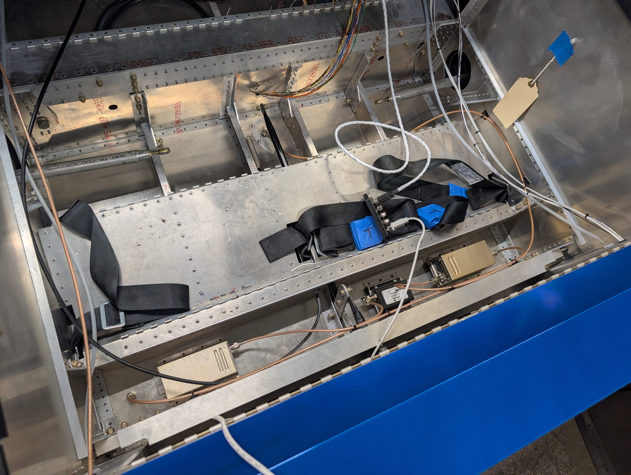
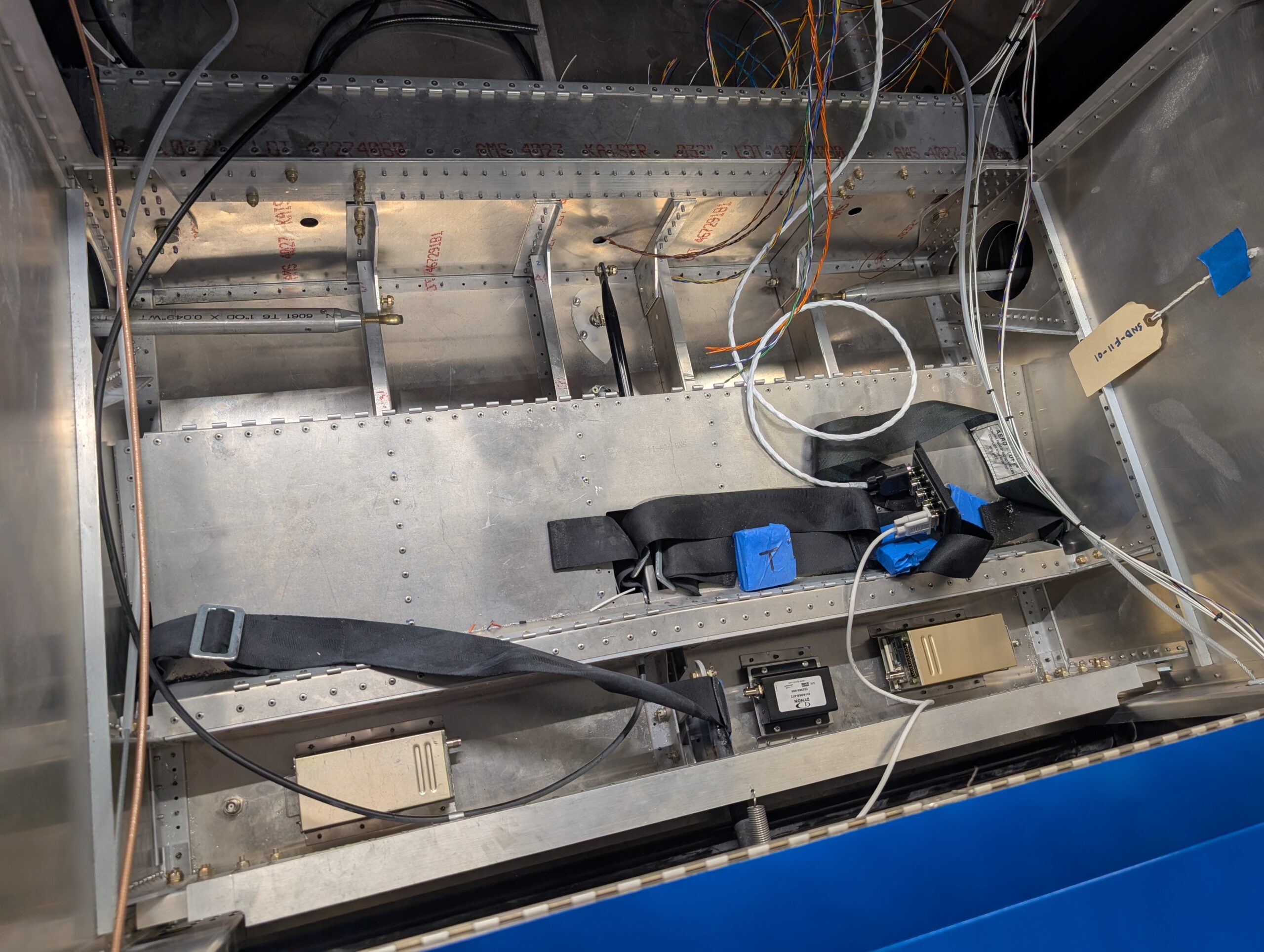
Fabricated transponder and com antenna cables from parts then installed into airframe. Secured cables to rear spar carry through with adhesive pads. Hours Worked: 1.85

Cowl Fitment – Part 3
Aligned the cowl into its final place then pilot drilled side hinges to cowl. Initially only pilot drilled a few holes due to space constraints. Pilot drilled a few holes in the bottom cowl hinge half by using flashlight method to locate holes through the fiberglass. Removed cowl and hinges from the airframe then finished…
Cowl Fitment – Part 2
Decided to solve oil cooler clearance issue by moving oil cooler up by about 5/8″. Removed oil cooler bracket from bottom of engine and remade bracket from 1.5″ x 1.5″ aluminum angle stock with shorter leg. Installed new bracket on bottom of engine with Loctite 242 then reinstalled oil cooler to new bracket. Reinstalled lower…
Cowl Fitment – Part 1
Began fitment of lower cowl by marking out locations for gear legs and fuel drain. Slid lower cowl into place and measured front face of cowl offset by approximately 1″. Trimmed back edges of cowl 1/2″ at a time while moving cutouts forward at the same time. Refit cowl and determined that proper forward alignment…
Fuselage Floor Avionics – Part 1
Clecoed forward fuselage floor back onto fuselage to start under seat component layout. Made riser mounts for ADSB, transponder, and com boxes so that nutplates could be used out of scrap aluminum. Riveted mounts to fuselage floor behind seat pan and bolted SV-COM-T25, SV-ADSB-472, and SV-XPNDR-261 units into place. Drilled holes for transponder and ADS-B…
Flap Rigging
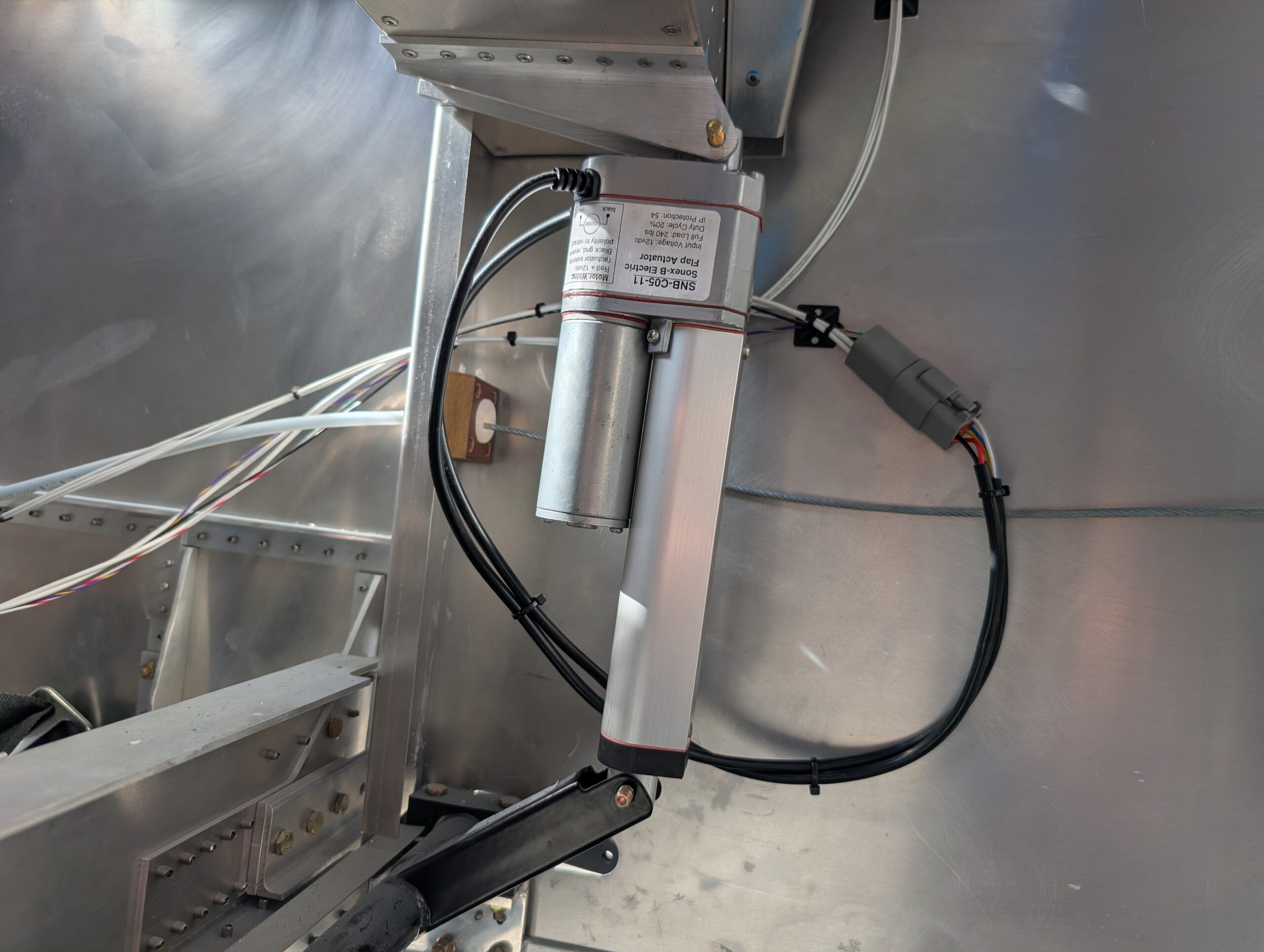
Began rigging flaps for final installation by trimming flap pushrod length from 3″ to 2″ to allow more adjustment of rod ends. Removed flap motor from drive tube for easier access and started by testing position of LH flap. Adjusted lower pushrod end to achieve full-up flap neutral position of 2 59/64″ measured from the…
Wing Installation – Part 1
With help, mounted left and right wing assemblies onto fuselage. Attempted to add weatherstripping on inside edges of wings but there wasn’t enough clearance; will likely seal gaps with tape later on. Before sliding wings fully together, connected wing root connectors and pitot/AOA connections. Opted to use drilled hardware and cotter pins for wing bolt…
Final Wing Assembly
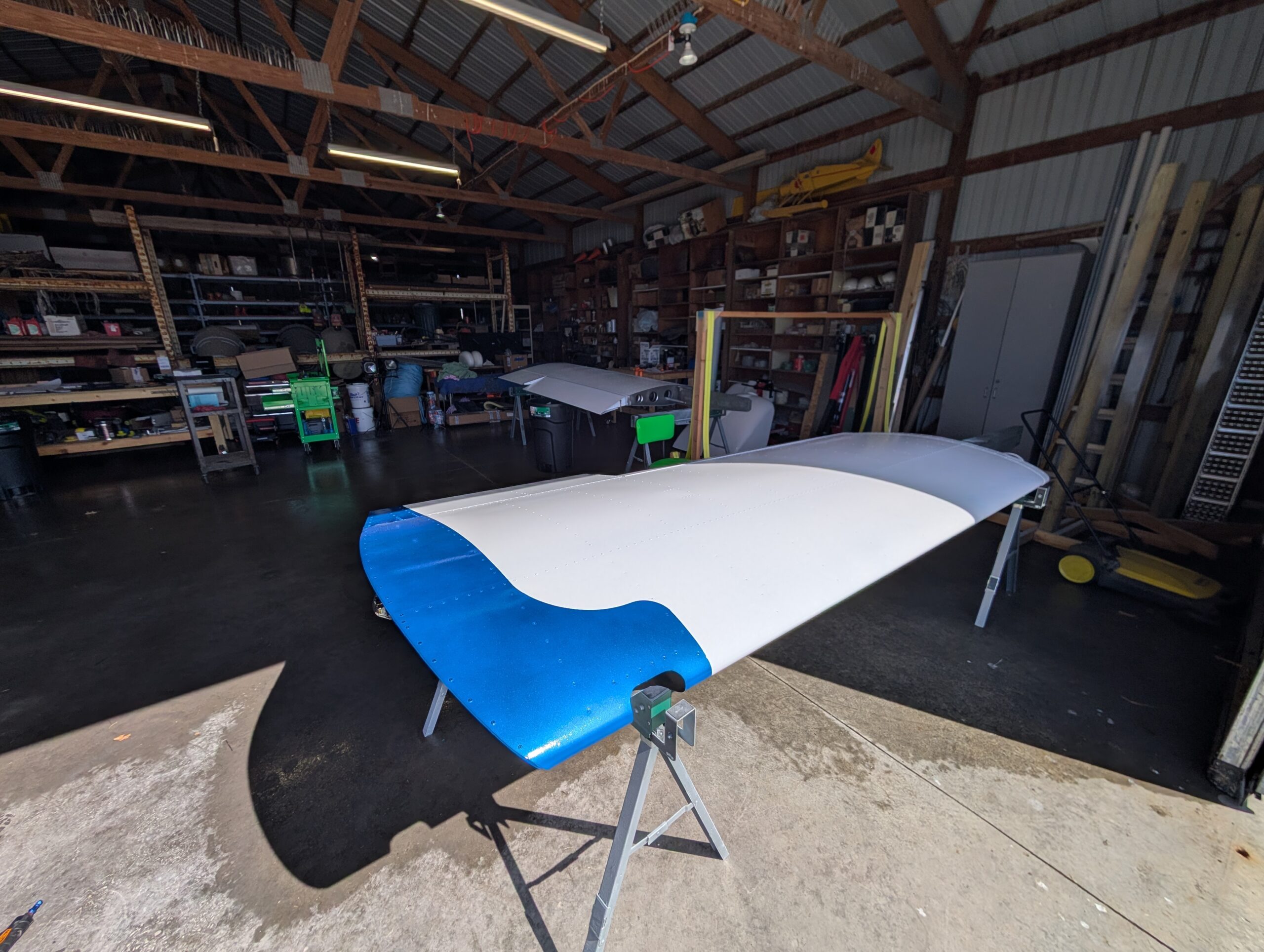
Removed wings from wing stand and set onto saw horses. Assembled aileron push rods and filed thrust bearings down for 0.01″ clearance between bushing and bell crank plate and installed assembly onto LH aileron. Slightly enlarged counterweight opening in rear spar for bolt clearance then attached LH aileron to wing with piano hinge rod. Drilled…
Flap Motor Wiring
Partially wired flap switch on bench and added extra leads to make installation into panel easier. Installed flap switch into panel and connected ground and power wires. Decided to share ground with alternator reset switch so ran additional wire to reset switch. Used Molex connector for reset switch which contacted outside terminals at the right…
Engine Baffles – Part 1
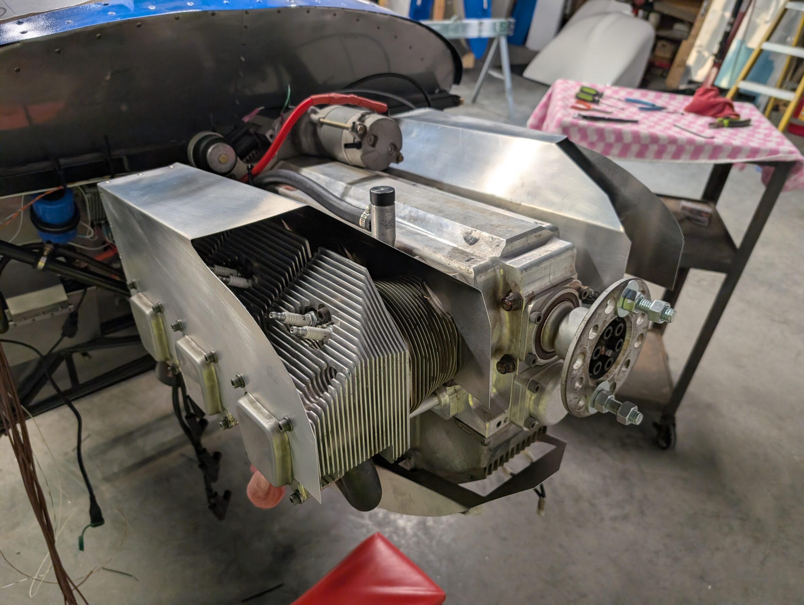
Crimped new 4 gauge starter cable onto cut portion with heat sink. Installed starter motor onto engine and ran cable down the oil breather line to starter solenoid. Briefly checked starter function. Created 4 intercylinder baffle plates based on forum recommendations and hung them underneath cylinders with safety wire and welding rod. Assembled right and…
Aileron Balancing
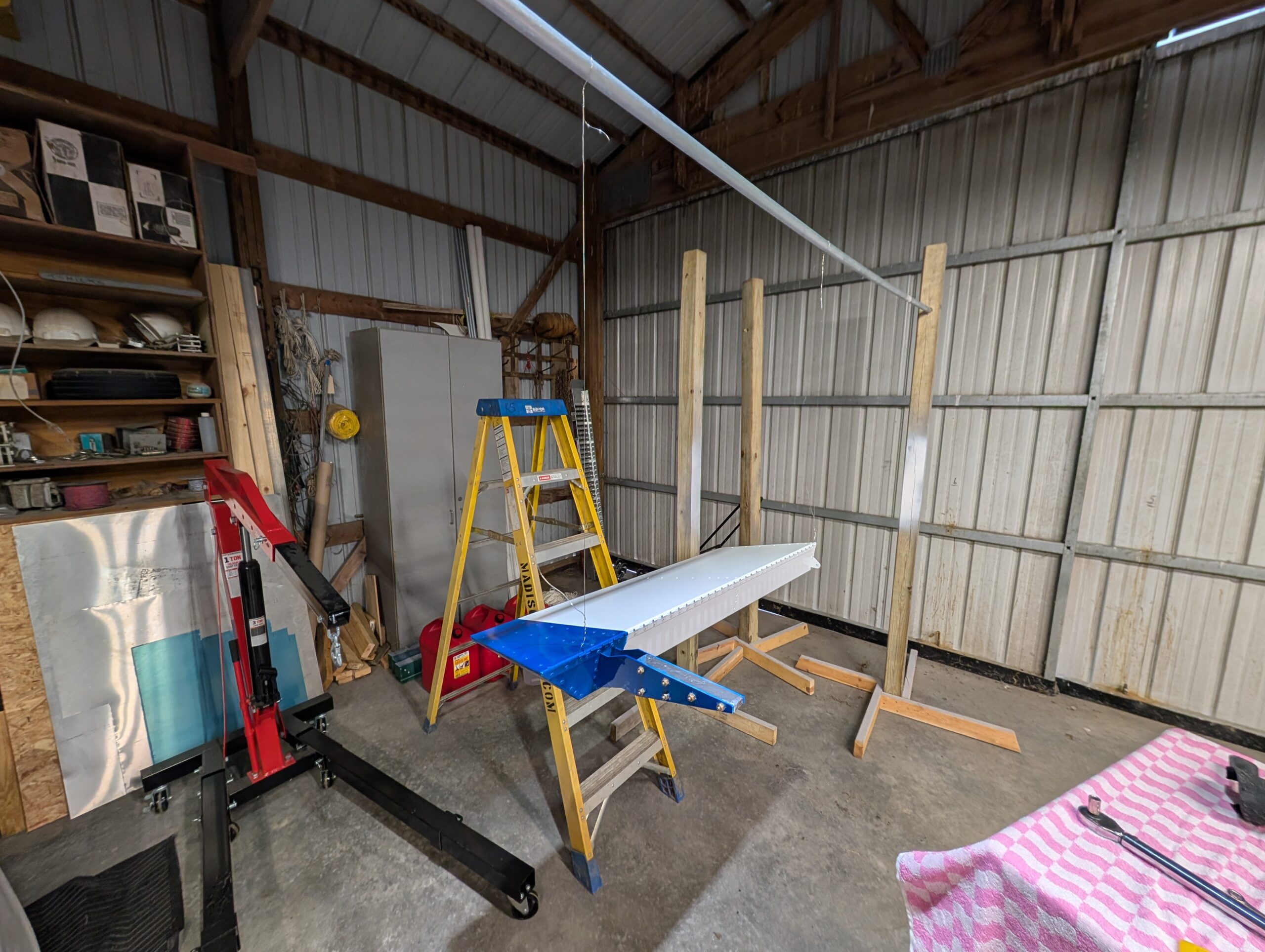
Assembled paint fixture to hang ailerons from. Suspended RH aileron from fixture and bolted lead counterweight onto bracket. Checked levelness per plans and did not need to remove any material. Repeated process for LH aileron and drilled one 3/16″ hole on top of lead counter weight approximately 1/2″ deep to achieve balance. Ailerons now complete…