AN960-416
-
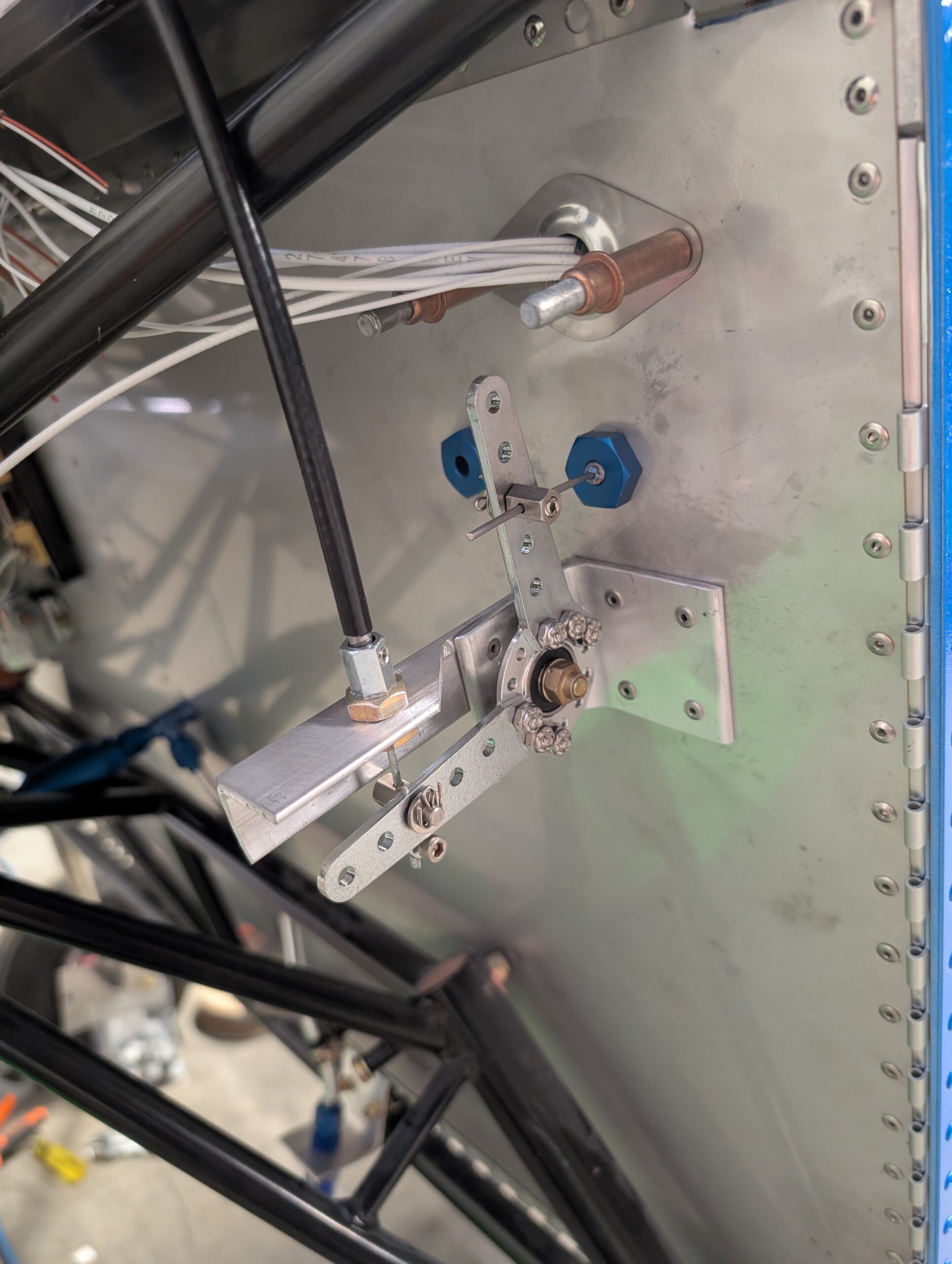
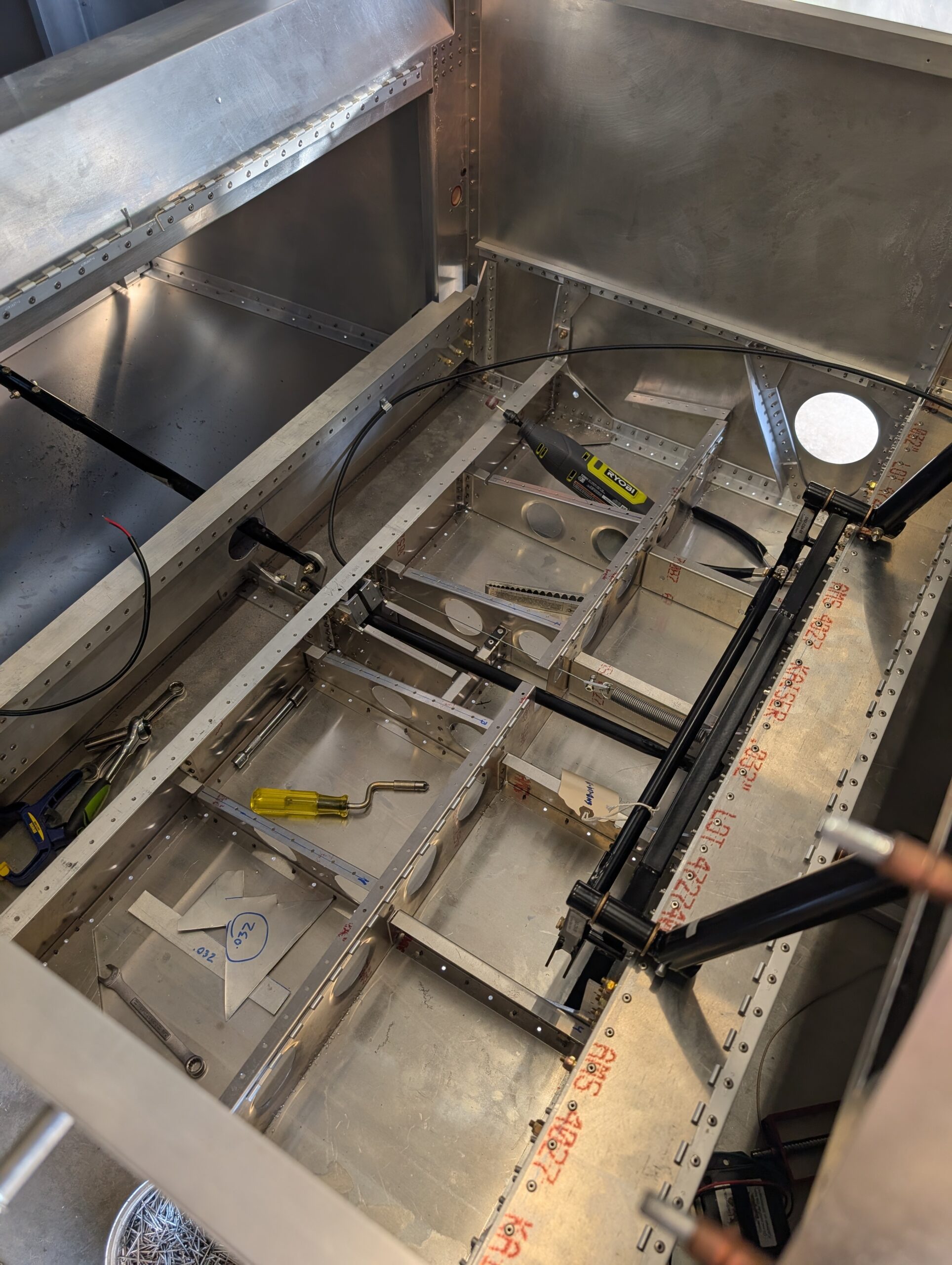
Throttle Bell Crank – Part 2
Installed throttle cable in center panel area. Located throttle and mixture cable pass-through locations on firewall and prepared holes for cable bulkheads. Installed both cable safes. Located throttle bellcrank assembly based on throttle cable pass through then transferred mounting holes onto firewall. Cleaned up bellcrank assembly then riveted pieces together and to firewall. Tested cable…
-
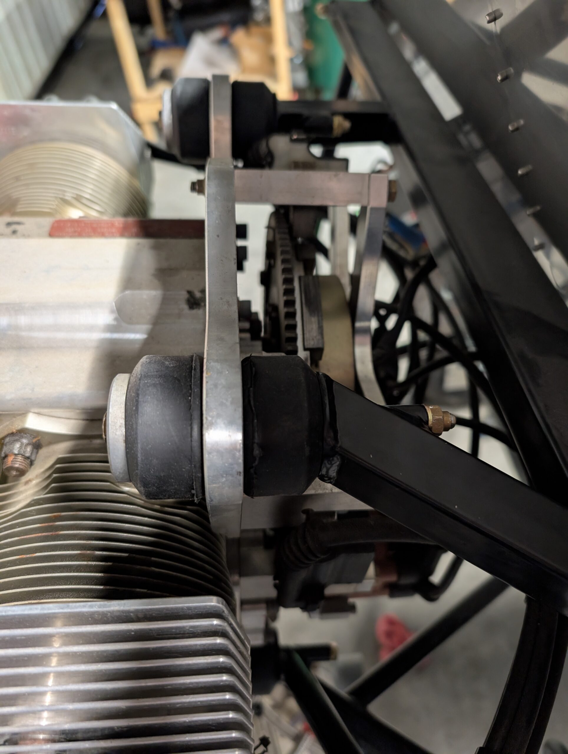
Engine Hardware Replacement
Replaced temporary engine mount hardware (too long) with properly sized AN4-46A bolts and AN363 nuts.
-
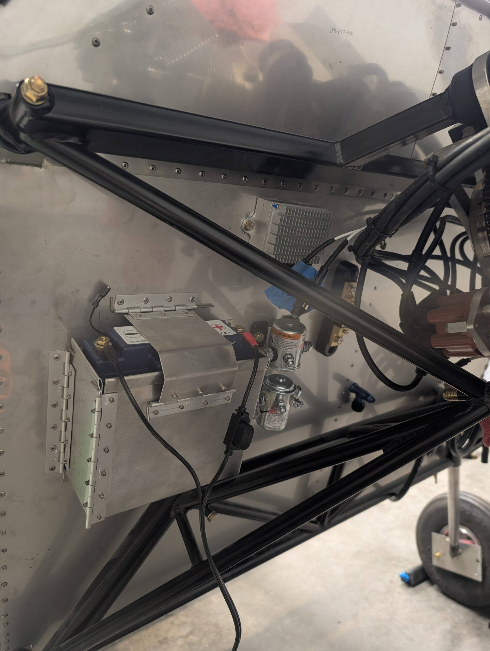
Mounting of FWF Electrics
Began mounting FWF components on firewall by laying everything out in a logical order then marking and drilling mount holes. Installed nutplates for all fixtures to enable easy replacement in the future. Temporarily mounted starter solenoid and voltage regulator for now pending proper bolts and ring terminals for ground wires. Hours Worked: 2.87
-
Rudder Control System – Part 2
Heated up C01-03 rudder spring stock with propane torch and bent springs to specs in plans. Previously tried to bend springs without heat and spring steel broke rather than bent. After installing springs into fuselage, discovered that plan dimensions were a little long and resulted in rudder pedals not returning to neutral. Shortened springs by…
-
Elevator Control System – Part 1
Temporarily installed control stick assembly. Pressed SF-812-3 bushings into stick to idler bar and control frame then installed idler hardware permanently and stick hardware temporarily. Verified freedom of movement and clearances with idler bar. Pressed bushing into elevator push rod ends, clecoed forward pushrod support to cross ties, and checked clearance of elevator push rod.…
-
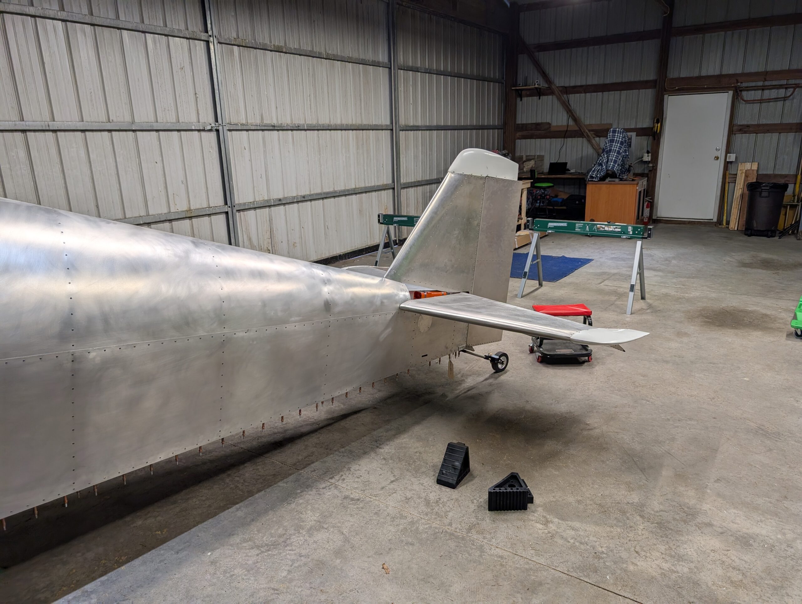
Tail Installation – Part 3
Mocked up ELT location on rear shear web and marked vertical stabilizer on where skin needs to be trimmed. Removed vertical stabilizer and marked out mounting hole location on shear web. Trimmed vertical stabilizer skin and riveted ELT mount and clamps to fuselage. Painted elevator horn with spray paint. Reattached vertical stabilizer with AN3 and…
-
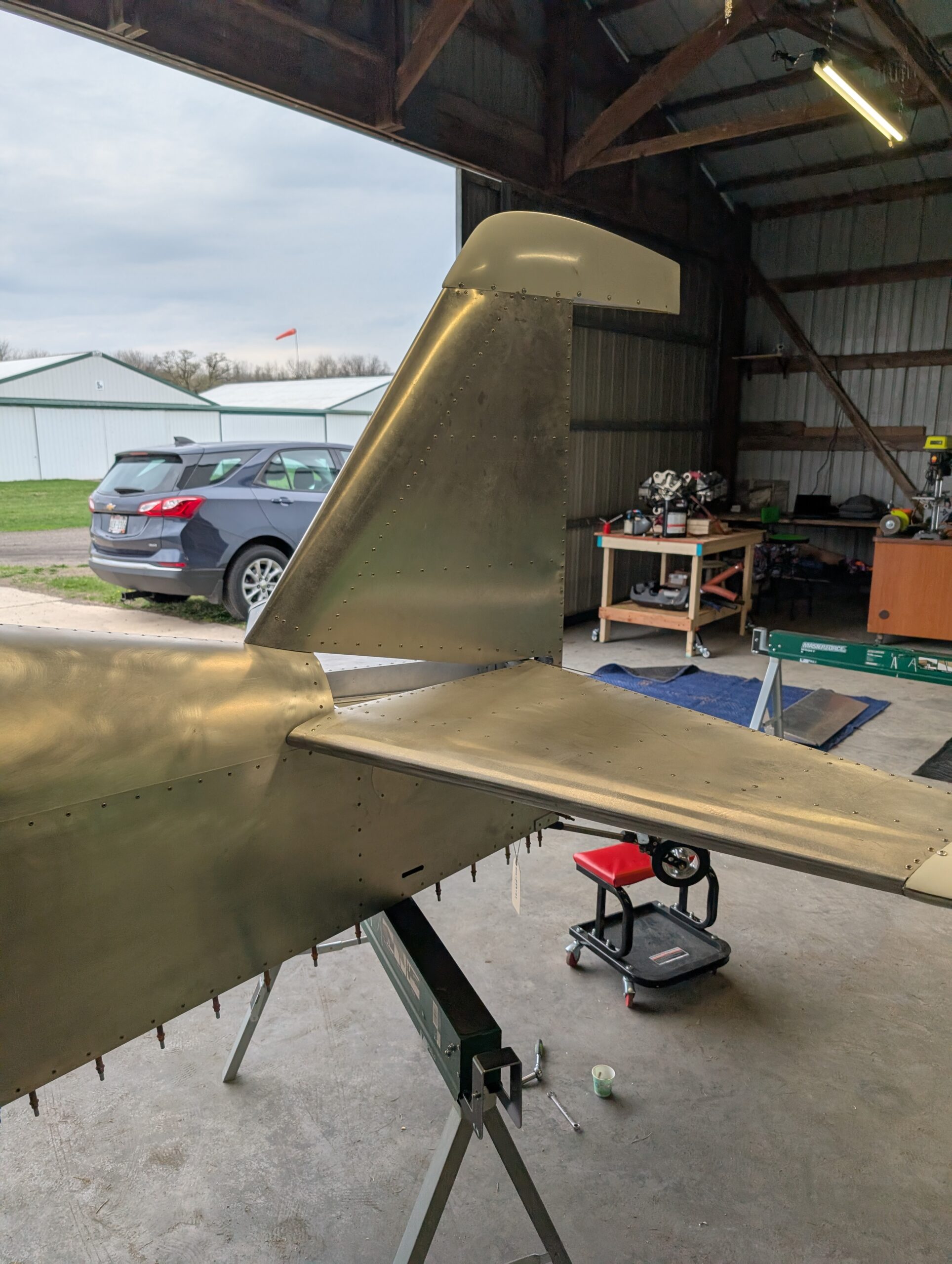
Tail Installation – Part 1
Began tail surface installation by moving tail surfaces from house to hangar. Discovered that horizontal stabilizer skins were installed upside down and that the bottom skins would need to be trimmed to fit around fuselage tail cone. Using the top side skin as a reference, trimmed bottom skin to clear fuselage tail cone. Will need…
-
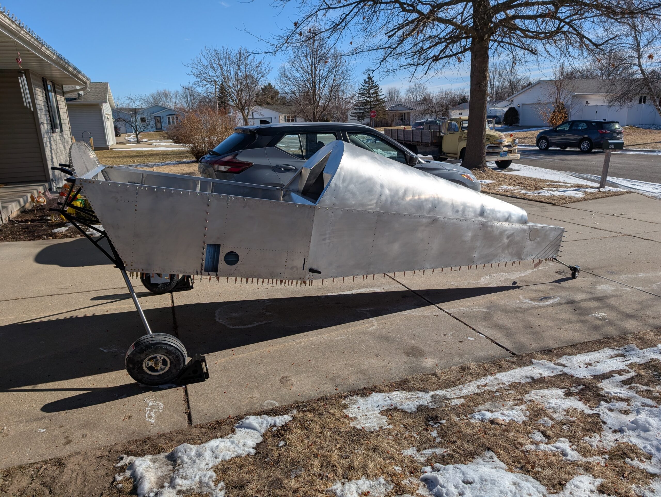
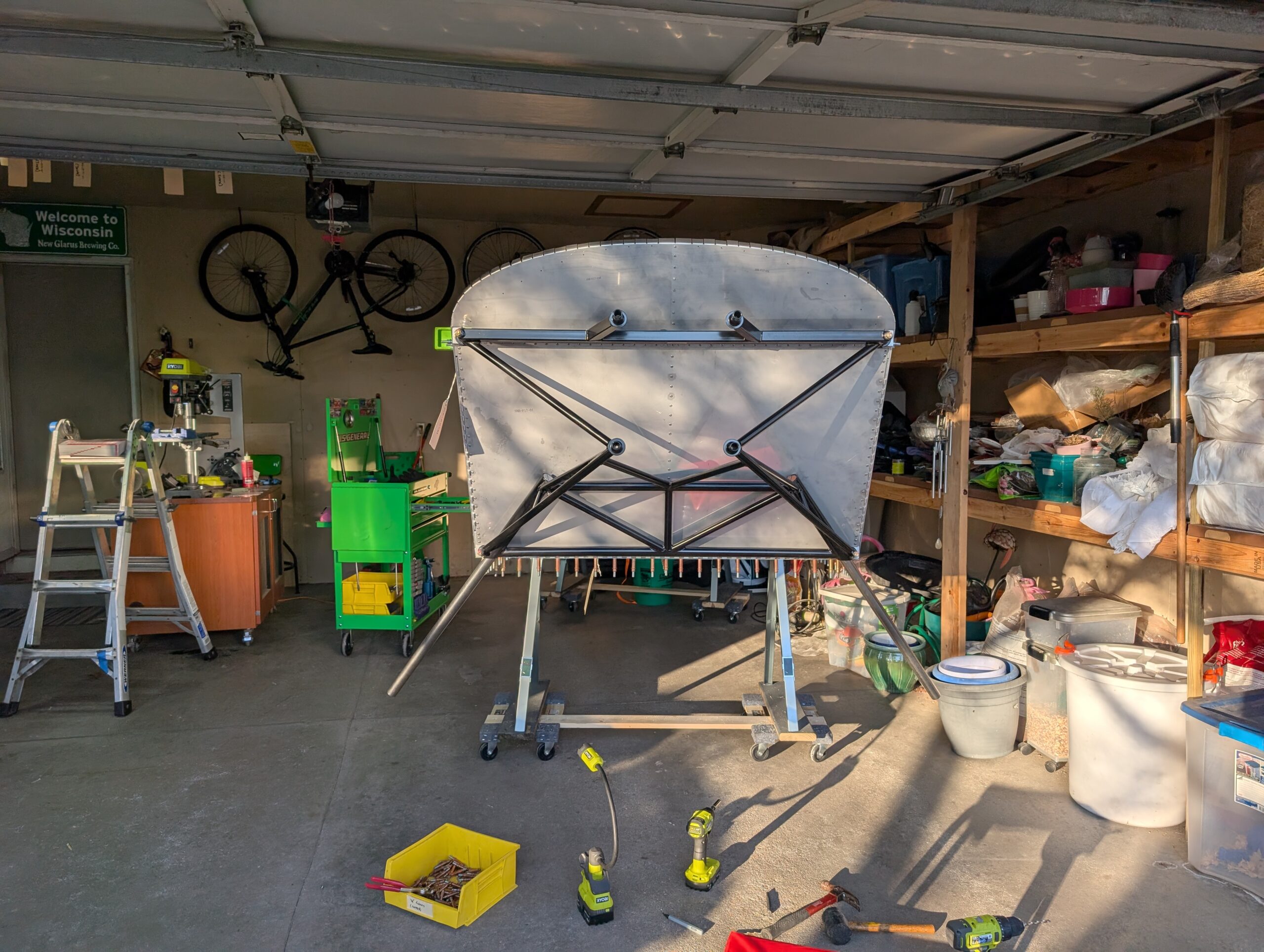
Tailwheel Installation – Part 2
Deburred tail wheel and spring holes and installed AN4 hardware through tail wheel assembly. Reinstalled clecoes on aft fuselage floor and took off of saw horses. Rolling chassis complete! Hours Worked: 1.26
-
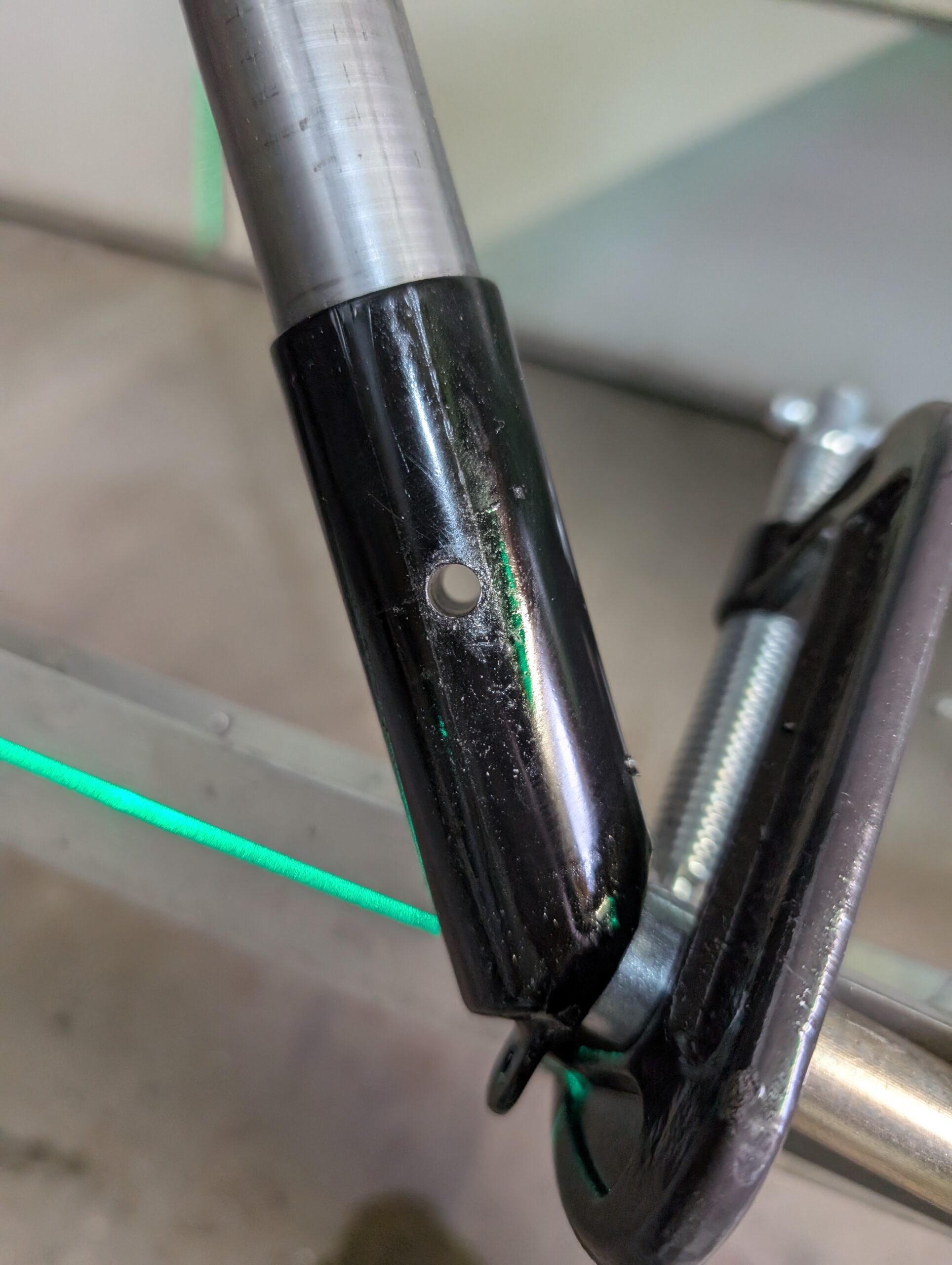
Main Landing Gear Installation – Part 3
Drilled motor mount hole in new RH gear leg same as previous but used V block in drill press to ensure squareness. Deburred hole and attached new RH gear leg to fuselage with AN4-30A bolt. Drilled 1/8″ pilot hole through new RH axle (one side only). Setup axle toe-in jig by clamping aluminum angle to…
-
Main Landing Gear Installation – Part 1
Started by setting up drill press to drill titanium legs. Opted to not trim gear legs and left the 1/8″ longer than plans. Drilled main gear legs using slowest speed on drill press and 1/8″ cobalt drill bit. After initial holes were drilled, updrilled holes to 1/4″. Deburred and sanded main gear leg holes in…
-
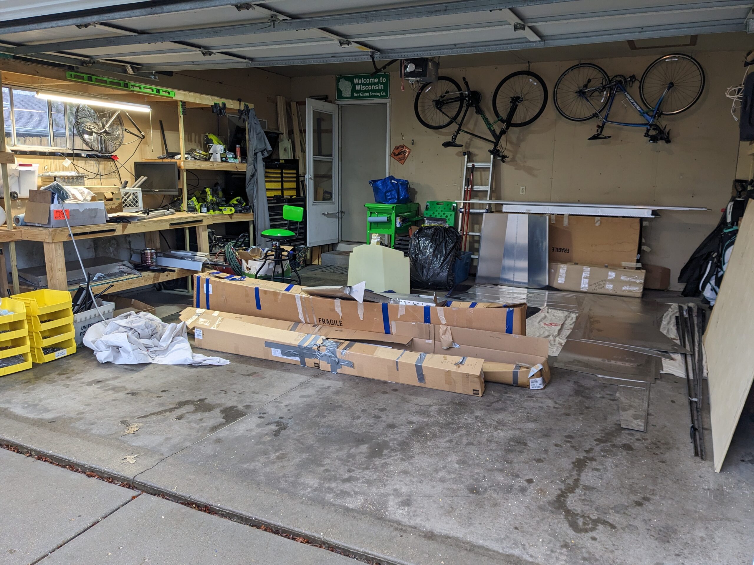
Initial Kit Inventory – Part 2
Inventory most of kit. Still need to organize tools and parts in small boxes Hours Worked: 8.50