SNB-E01: Avionics & Electrical

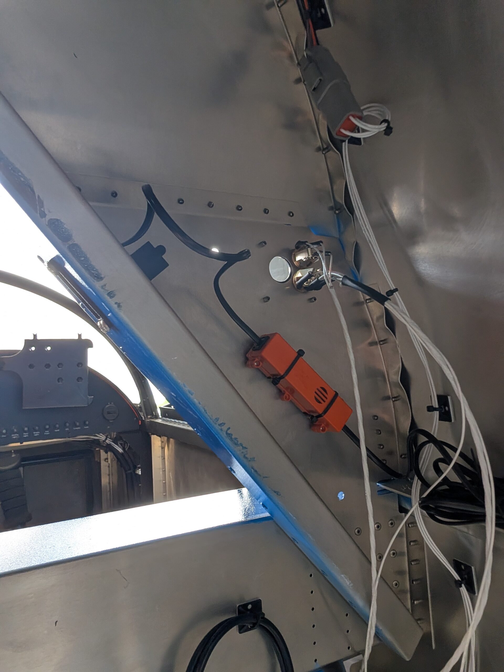
ELT Installation
Located and drilled hole for ELT antenna on aft portion of turtle deck. Secured antenna to fuselage then routed and connected coax cable from antenna to ELT. Cut hole in RH #1 former for RCPI and drilled mounting holes. Installed vertical faceplate and A544 alkaline battery into RCPI (battery expires 06/19/2031) then mounted RCPI onto…

Stick Grip Wiring
Installed control stick ground wire and autopilot ground wire in GB24 ground block. Ran and routed PTT wires from mic jacks to stick grip harness and began populating fuselage side of connector. Attached aux fuse block power and ground wires to fuse block. Ran smoke system control ground to stick and left extra length on…

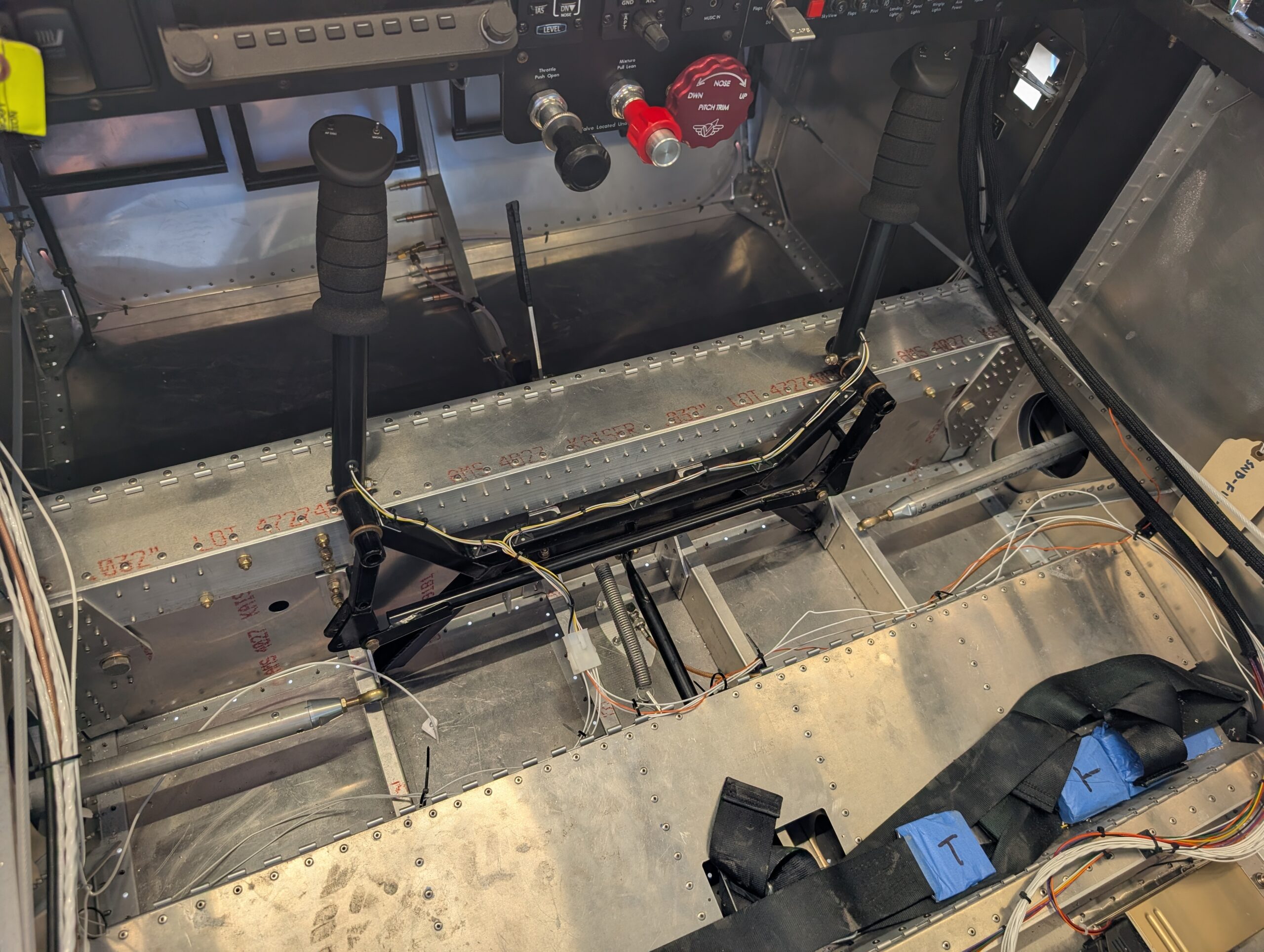
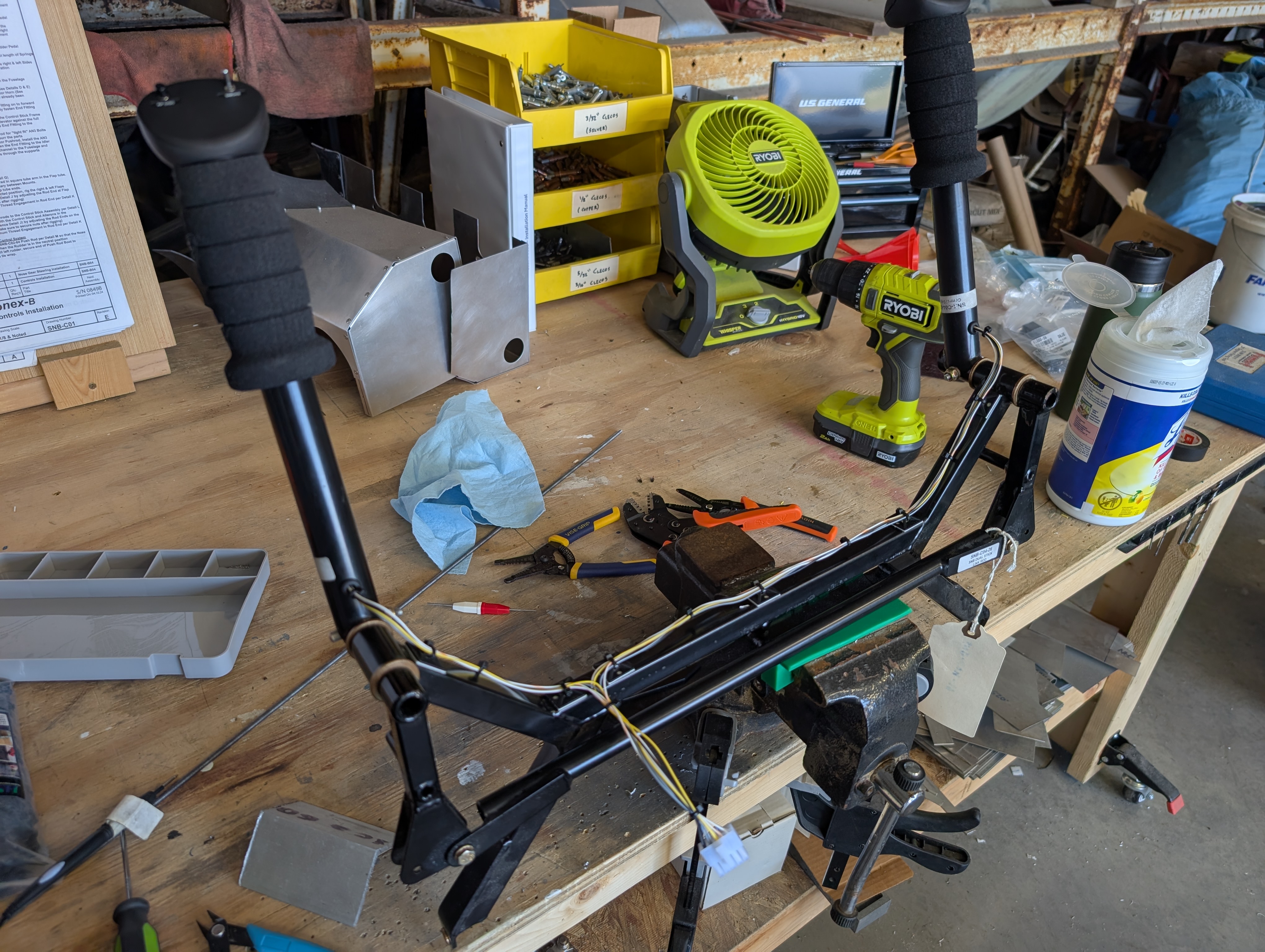
Stick Grip Installation
Finished securing wiring behind instrument panel and underneath sub-panel shelf. Drilled wire hole in bottom of both control sticks for stick grip wiring. Aligned stick grips and drilled pilot hole in grip and control stick. Updrilled holes and tapped stick for 8-32 set screw. Installed stick grip foam onto each control stick and fished wires…

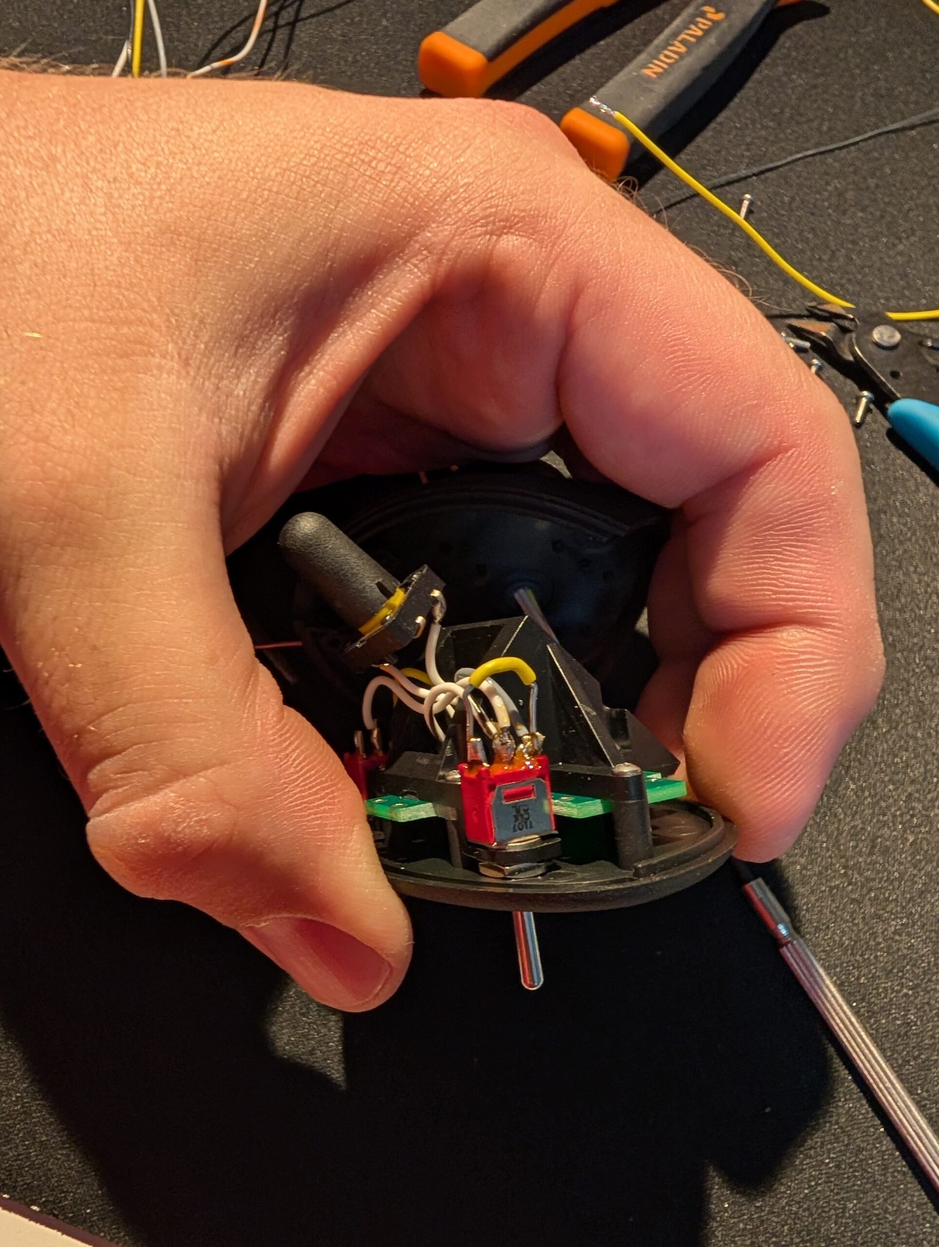
Stick Grip Modification
Opted to modify internal wiring inside the Ray Allen G403 stick grips in order to isolate PTT ground from other function ground. Removed screws in stick grip in order to remove circuit board from plastic housing. The default wiring is set up so that all functions share a common ground and the momentary/latched toggle switch…
Wiring Cleanup – Part 1
Installed aux power fuse block and SkyView splitter on underside of cross tie box with rivnuts. Worked on organizing and securing wiring under panel with zip ties and adhesive pads. Cut off unused EMS wires and secured into bundle in case of future upgrades. In spots where wire crosses over or under throttle controls, placed…
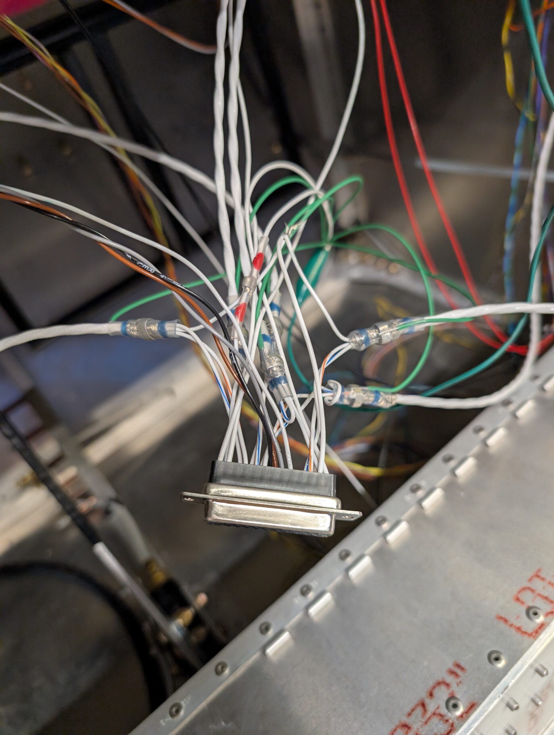
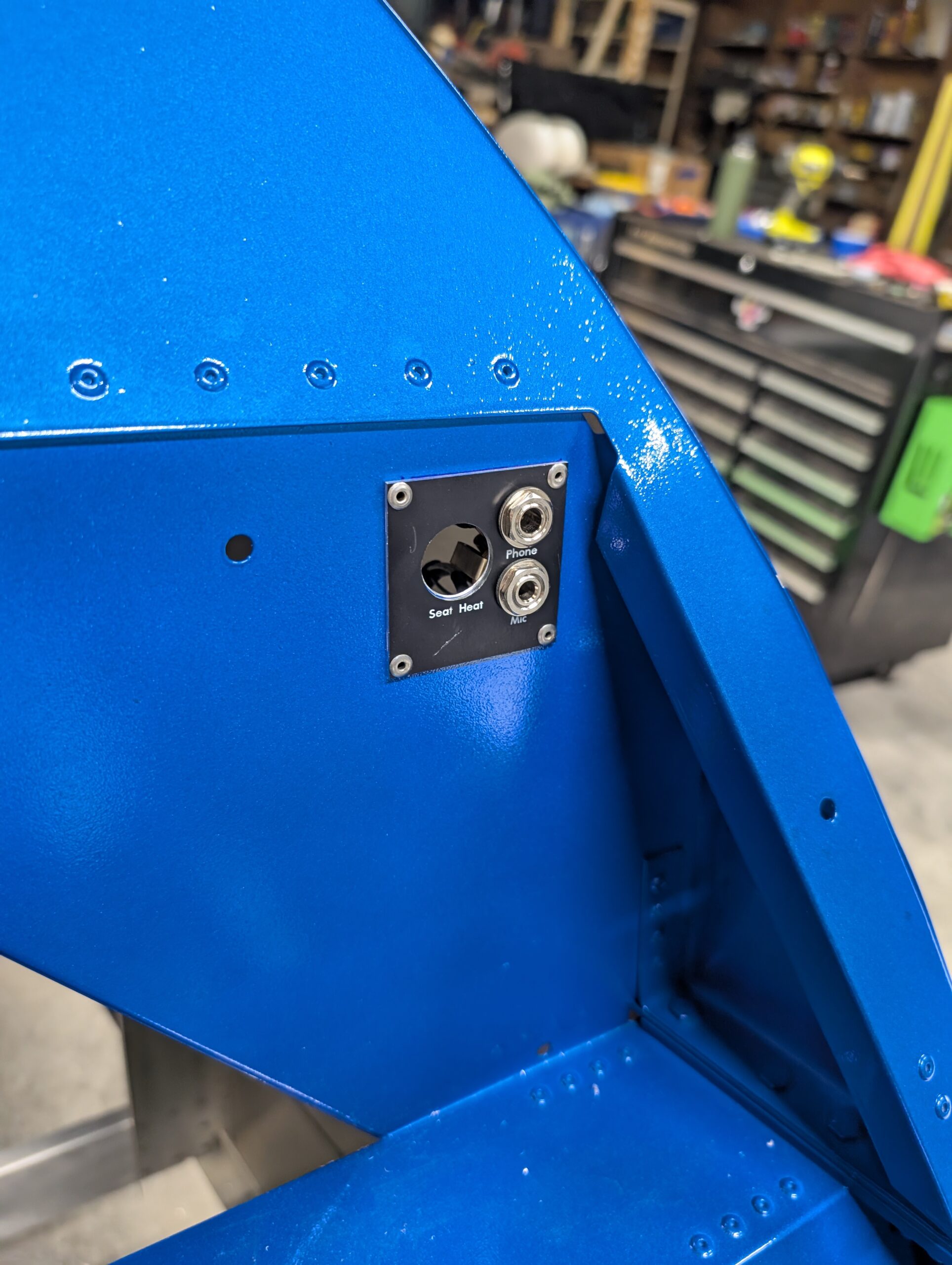
Intercom Harness Wiring – Part 2
Soldered shielded wire bundles onto copilot headset and passenger jacks. Installed both jacks on copilot side panel and routed wires to main intercom harness. Pinned connects at harness side then tested copilot side audio. Realized the the SkyView audio wires were routed under the throttle cable so had to unpin the four display wires and…
Intercom Harness Wiring – Part 1
Laid out aft cockpit panels on front formers and marked hole locations. Cut out mounting and component holes in formers, deburred, and riveted plates to fuselage. Measured out length of pilot side headset harnesses and cut three-wire shielded cable to length. Soldered harness onto headphone jack and used heat shrink to protect solder joints on…
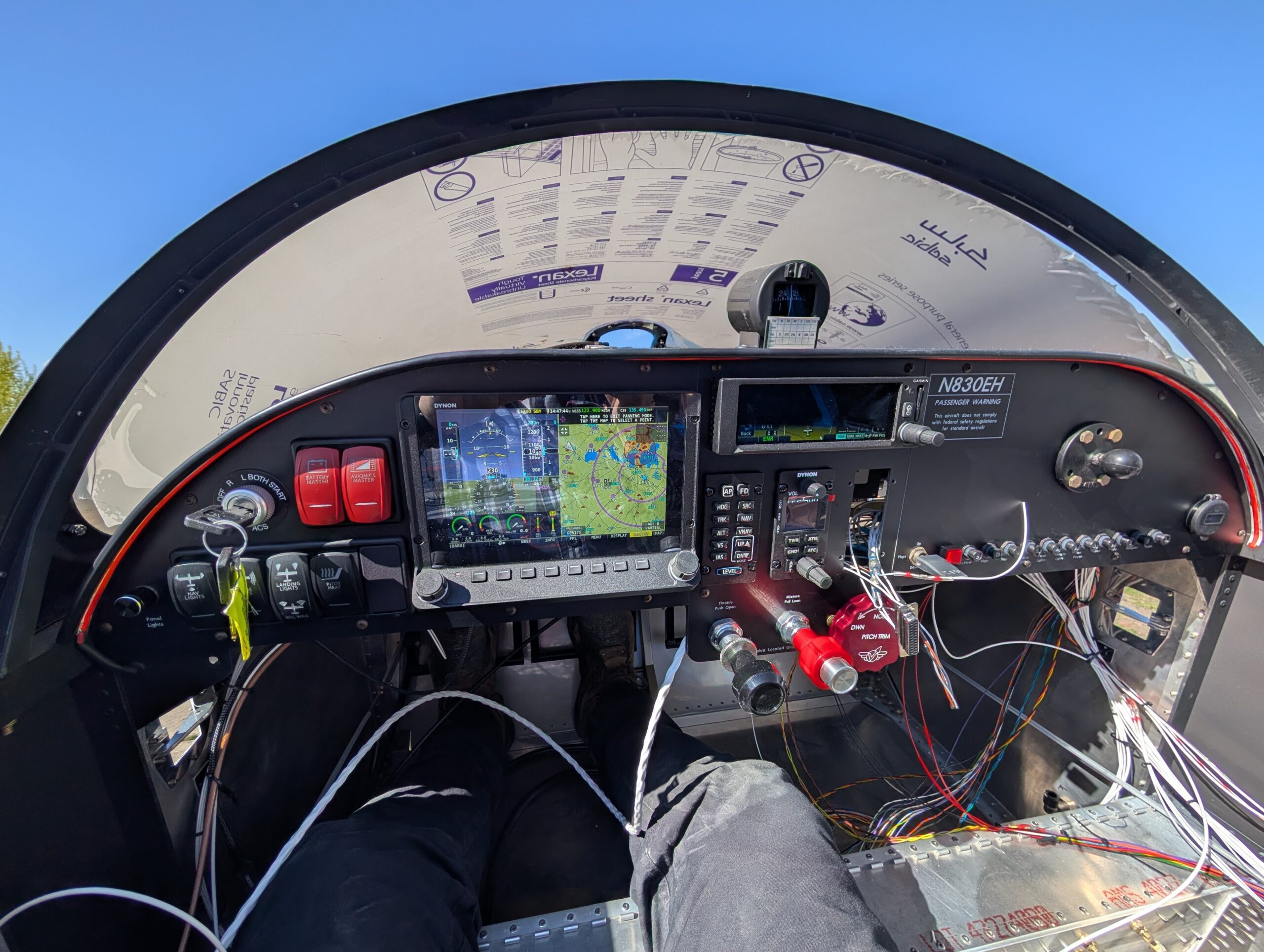
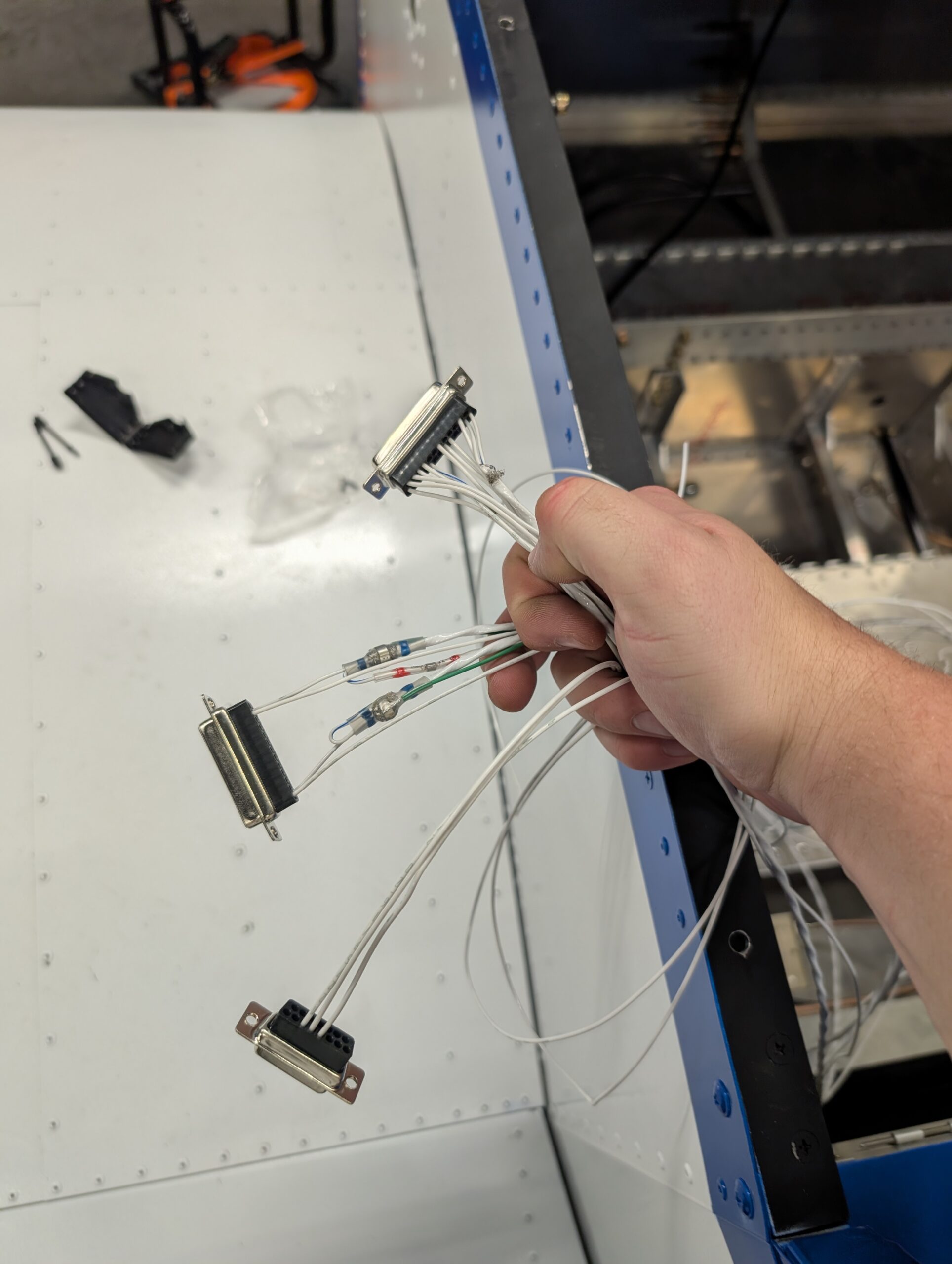
Transponder/ADS-B Harness Wiring
Removed RH side panel cover and finished wiring all circuit breakers and power feeds. Installed power outlet on RH side of panel. Left feed wires for autopilot and aux power panel for now. Installed pre-fabricated transponder and ADS-B harnesses and routed them on RH side of fuselage. Removed flip flop and squat switch wires from…
Radio Harness Wiring
Completed wiring harness for the SV-COM-T25 starting at the com radio side. Began harnesses for SV-COM panel and the SV-INTERCOM as well. Will finish populating other harness later. Hours Worked: 2.80
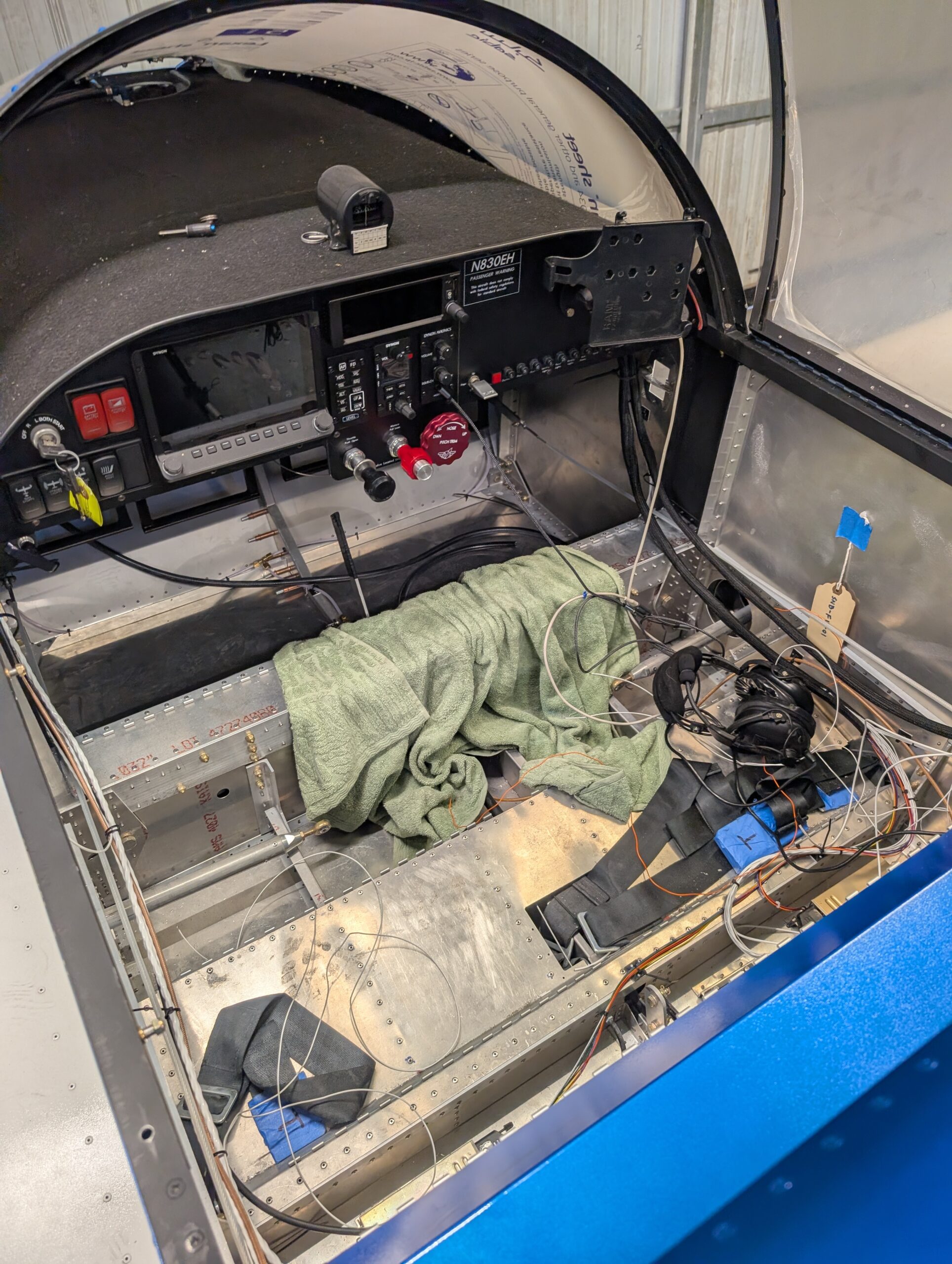
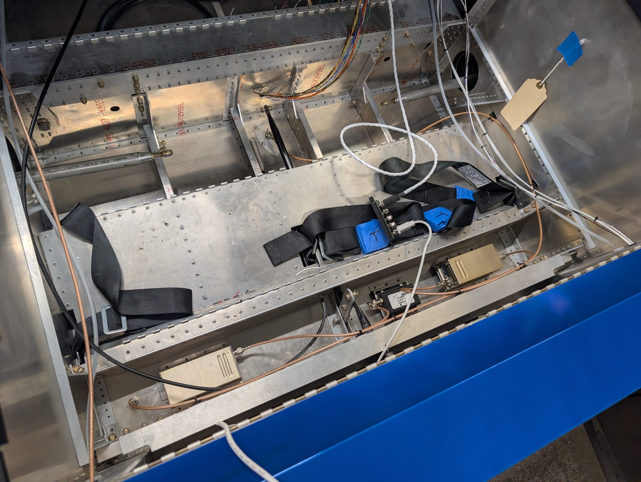
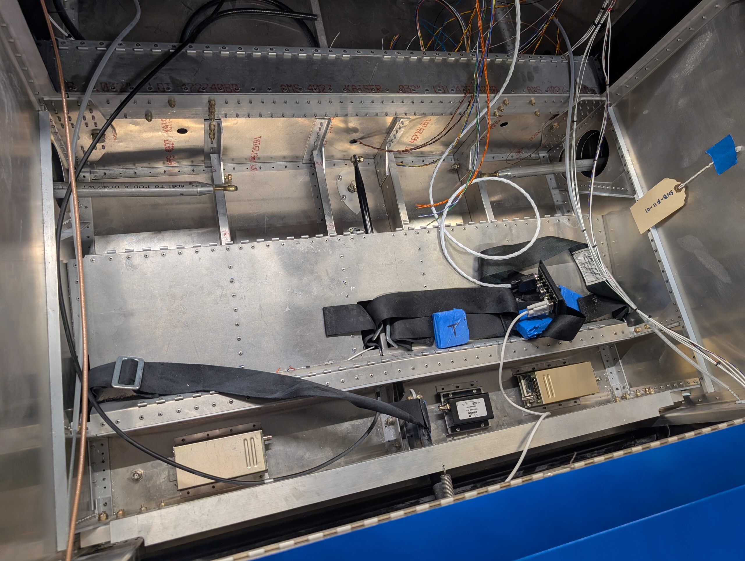
Fuselage Floor Avionics – Part 2
Fabricated transponder and com antenna cables from parts then installed into airframe. Secured cables to rear spar carry through with adhesive pads. Hours Worked: 1.85
Fuselage Floor Avionics – Part 1
Clecoed forward fuselage floor back onto fuselage to start under seat component layout. Made riser mounts for ADSB, transponder, and com boxes so that nutplates could be used out of scrap aluminum. Riveted mounts to fuselage floor behind seat pan and bolted SV-COM-T25, SV-ADSB-472, and SV-XPNDR-261 units into place. Drilled holes for transponder and ADS-B…
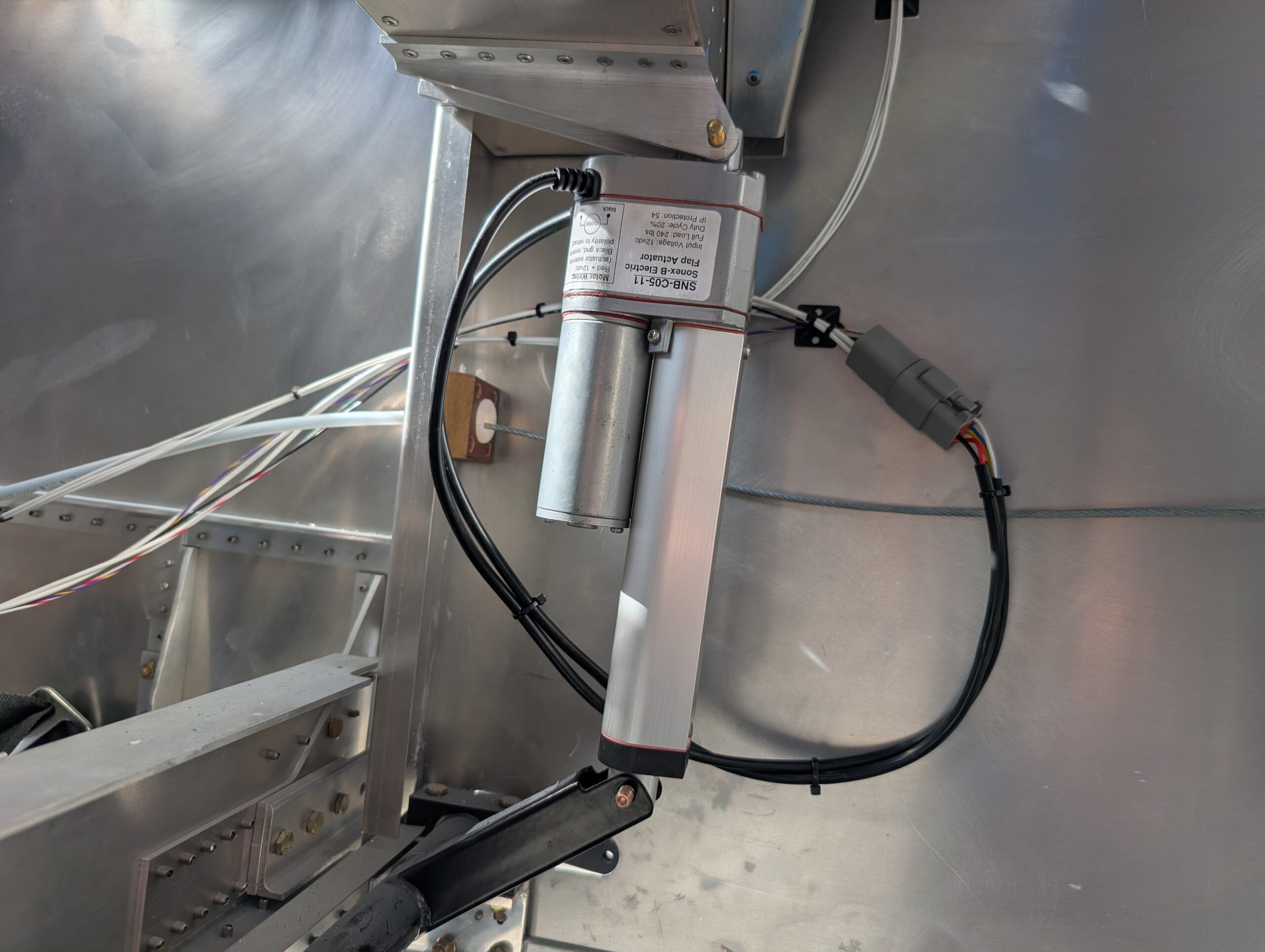
Flap Motor Wiring
Partially wired flap switch on bench and added extra leads to make installation into panel easier. Installed flap switch into panel and connected ground and power wires. Decided to share ground with alternator reset switch so ran additional wire to reset switch. Used Molex connector for reset switch which contacted outside terminals at the right…