emkrueger830

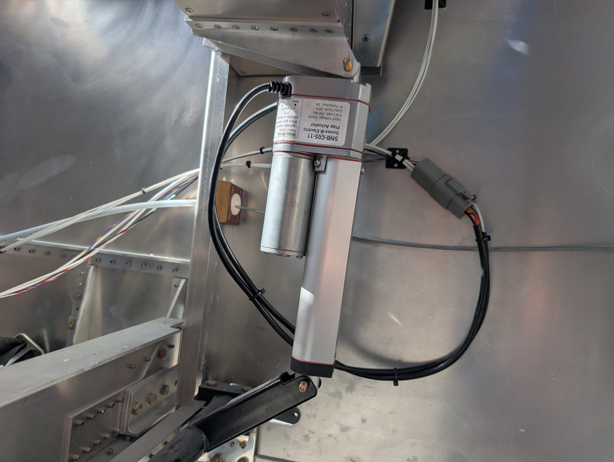
Flap Rigging
Began rigging flaps for final installation by trimming flap pushrod length from 3″ to 2″ to allow more adjustment of rod ends. Removed flap motor from drive tube for easier access and started by testing position of LH flap. Adjusted lower pushrod end to achieve full-up flap neutral position of 2 59/64″ measured from the…
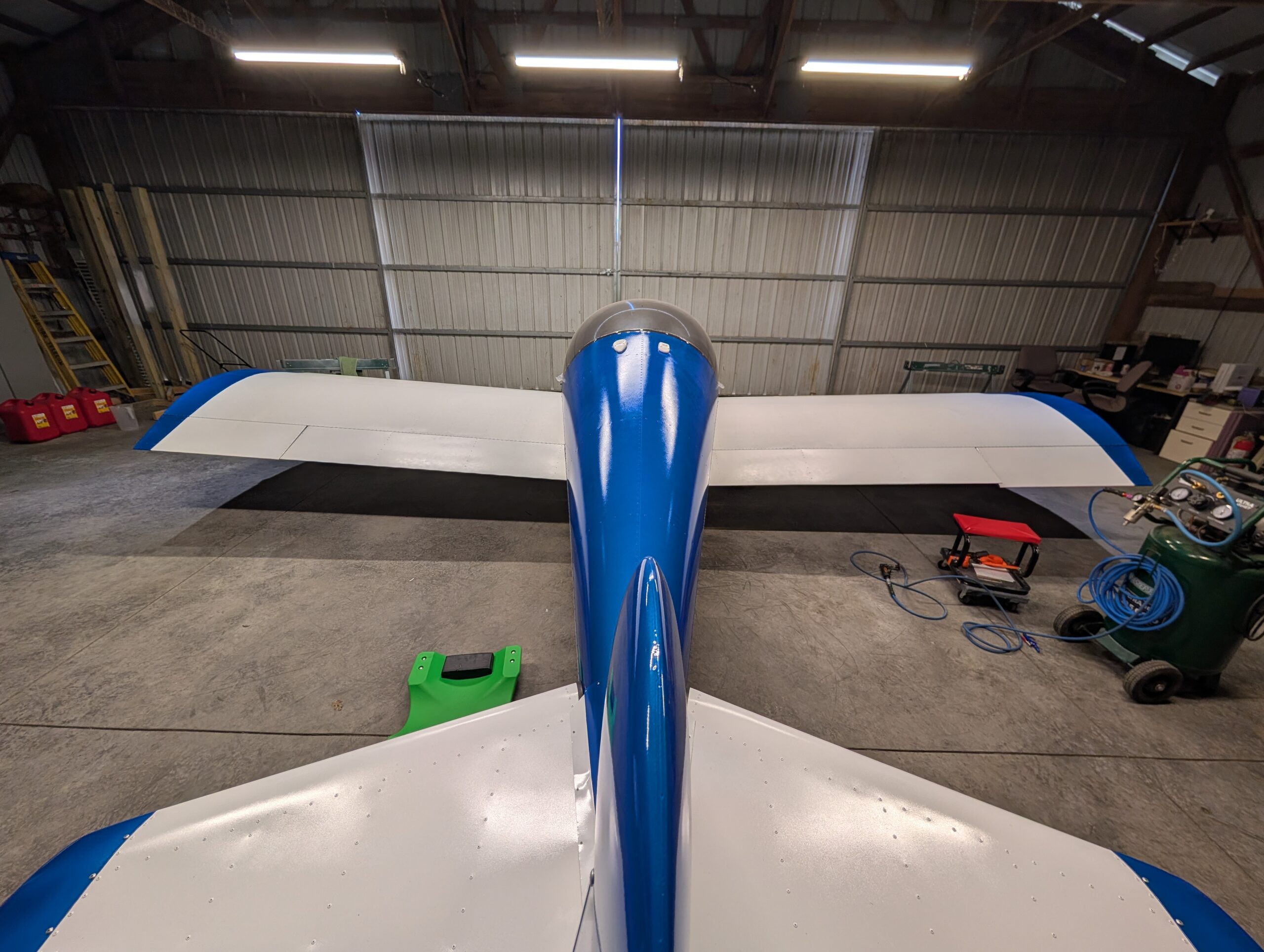
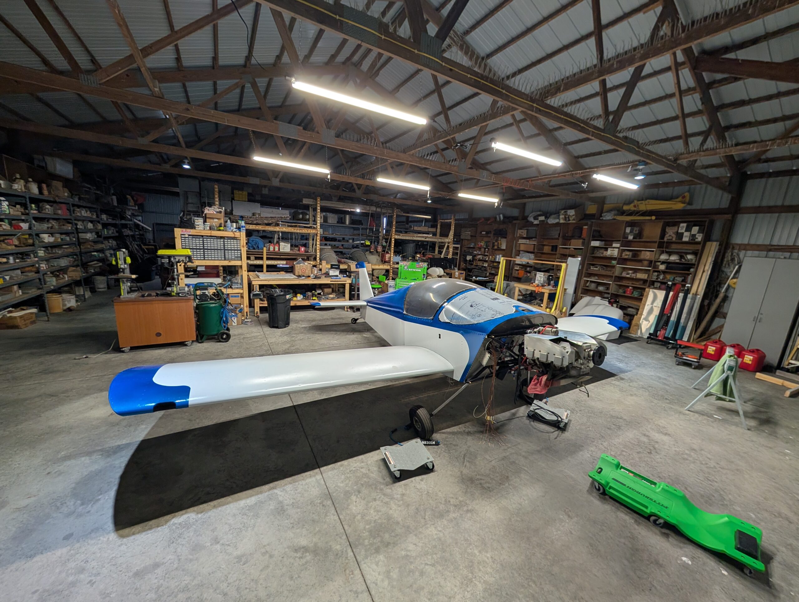
Wing Installation – Part 1
With help, mounted left and right wing assemblies onto fuselage. Attempted to add weatherstripping on inside edges of wings but there wasn’t enough clearance; will likely seal gaps with tape later on. Before sliding wings fully together, connected wing root connectors and pitot/AOA connections. Opted to use drilled hardware and cotter pins for wing bolt…
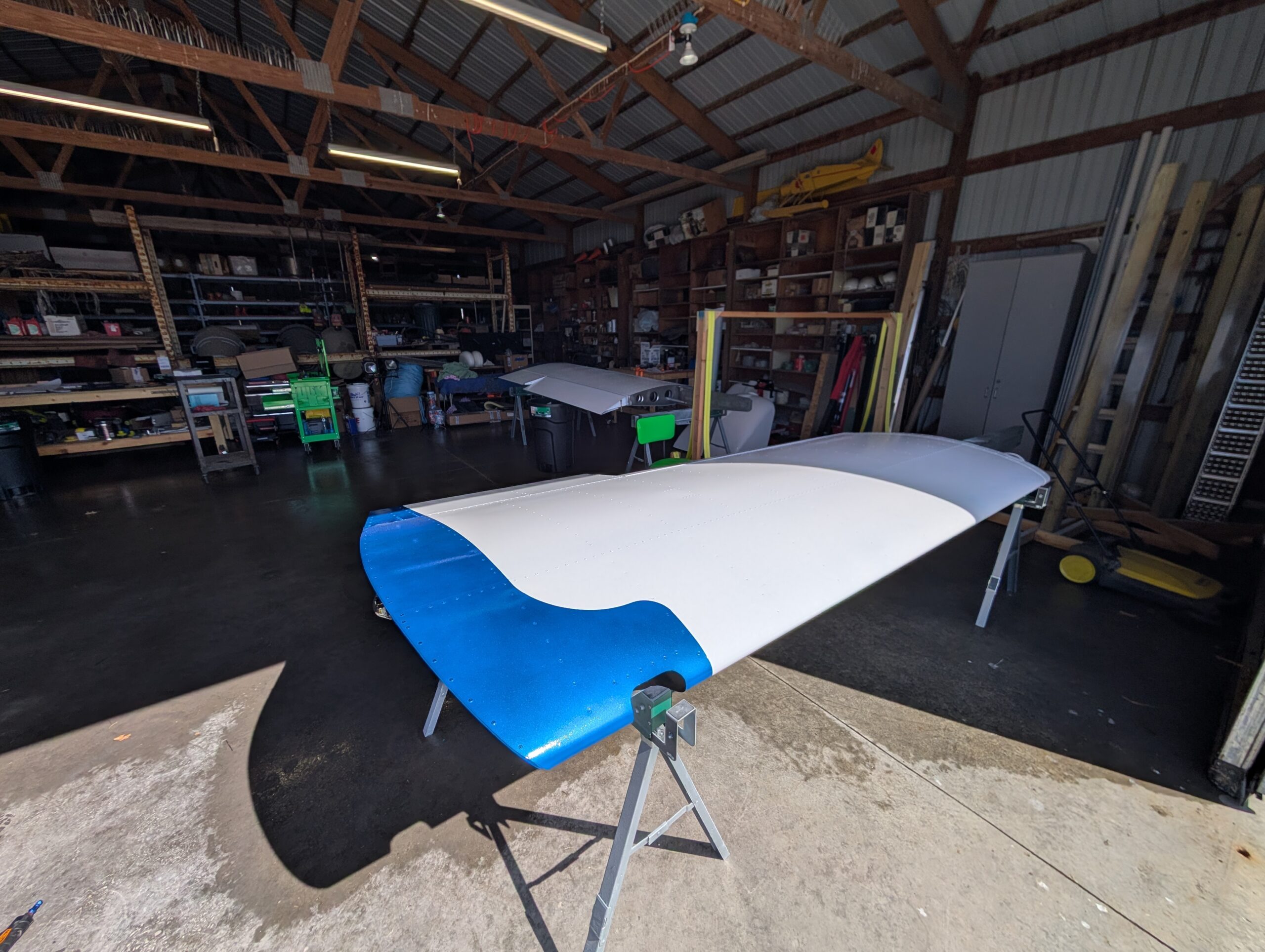
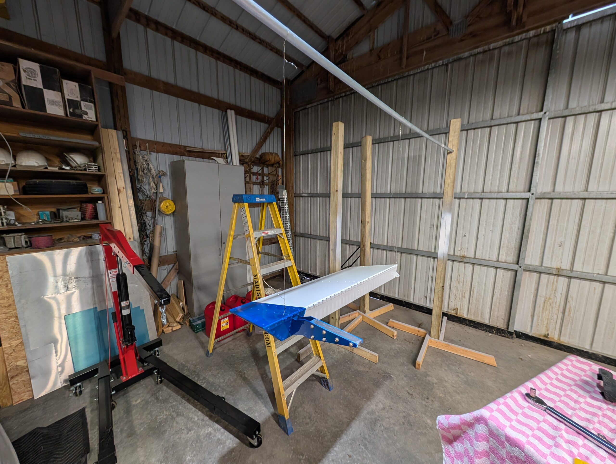
Final Wing Assembly
Removed wings from wing stand and set onto saw horses. Assembled aileron push rods and filed thrust bearings down for 0.01″ clearance between bushing and bell crank plate and installed assembly onto LH aileron. Slightly enlarged counterweight opening in rear spar for bolt clearance then attached LH aileron to wing with piano hinge rod. Drilled…
Flap Motor Wiring
Partially wired flap switch on bench and added extra leads to make installation into panel easier. Installed flap switch into panel and connected ground and power wires. Decided to share ground with alternator reset switch so ran additional wire to reset switch. Used Molex connector for reset switch which contacted outside terminals at the right…
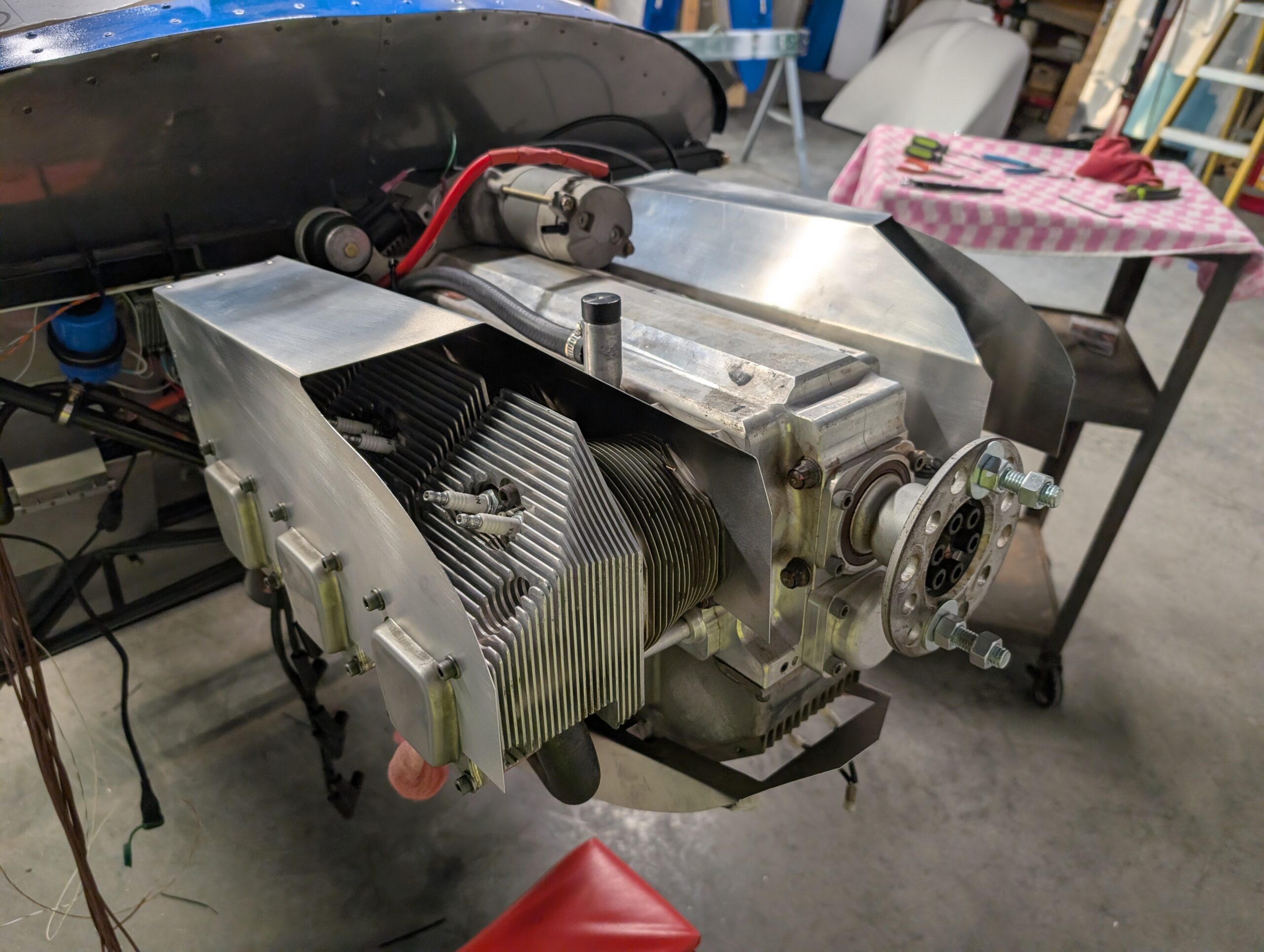
Engine Baffles – Part 1
Crimped new 4 gauge starter cable onto cut portion with heat sink. Installed starter motor onto engine and ran cable down the oil breather line to starter solenoid. Briefly checked starter function. Created 4 intercylinder baffle plates based on forum recommendations and hung them underneath cylinders with safety wire and welding rod. Assembled right and…
Aileron Balancing
Assembled paint fixture to hang ailerons from. Suspended RH aileron from fixture and bolted lead counterweight onto bracket. Checked levelness per plans and did not need to remove any material. Repeated process for LH aileron and drilled one 3/16″ hole on top of lead counter weight approximately 1/2″ deep to achieve balance. Ailerons now complete…

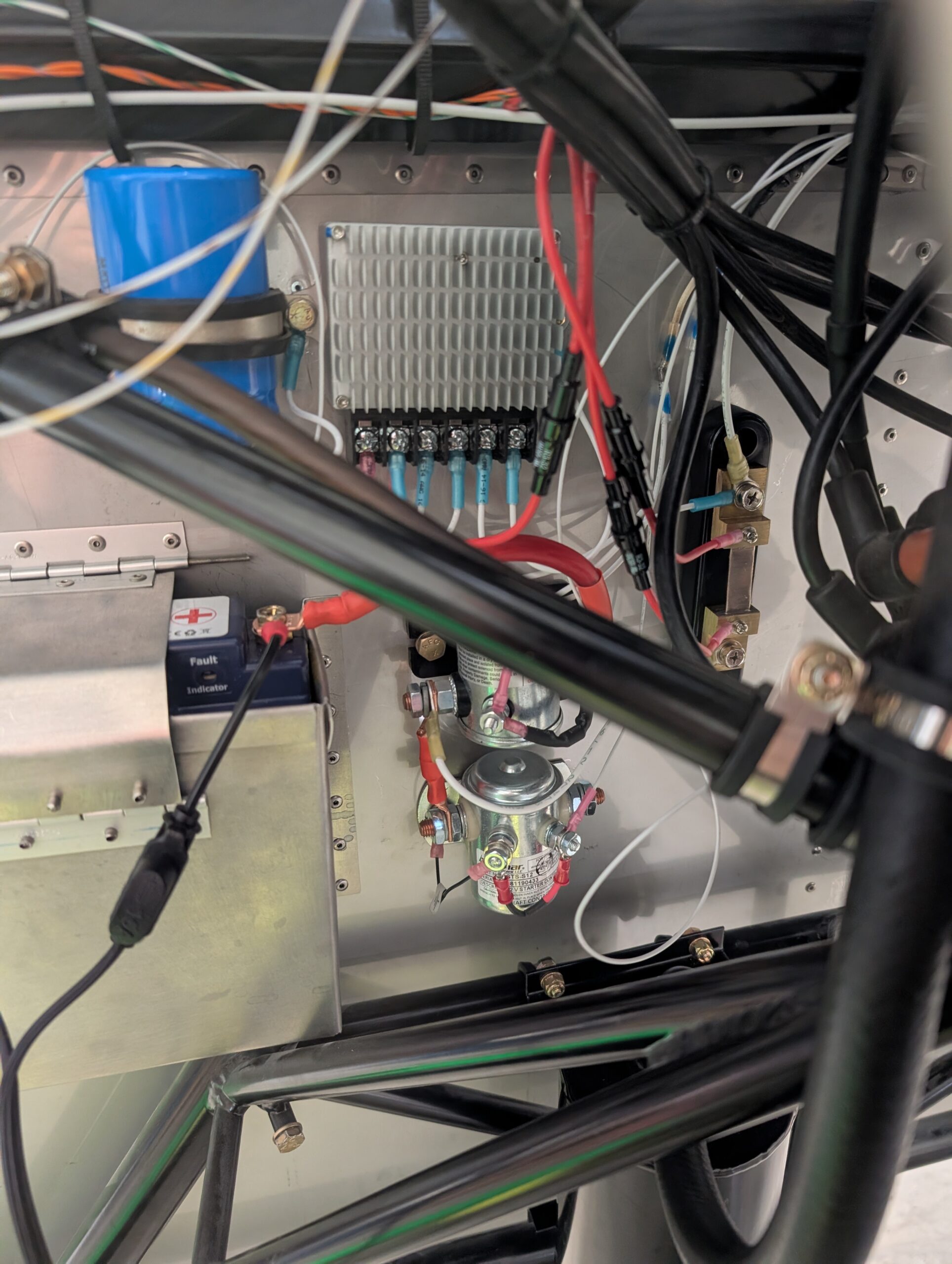
FWF Wiring – Part 3
Terminated amp shunt wires and tachometer lead by installing inline fuse holders with 1 amp fuses. Ran voltage regulator reset line from panel to voltage regulator. Hours Worked: 0.89
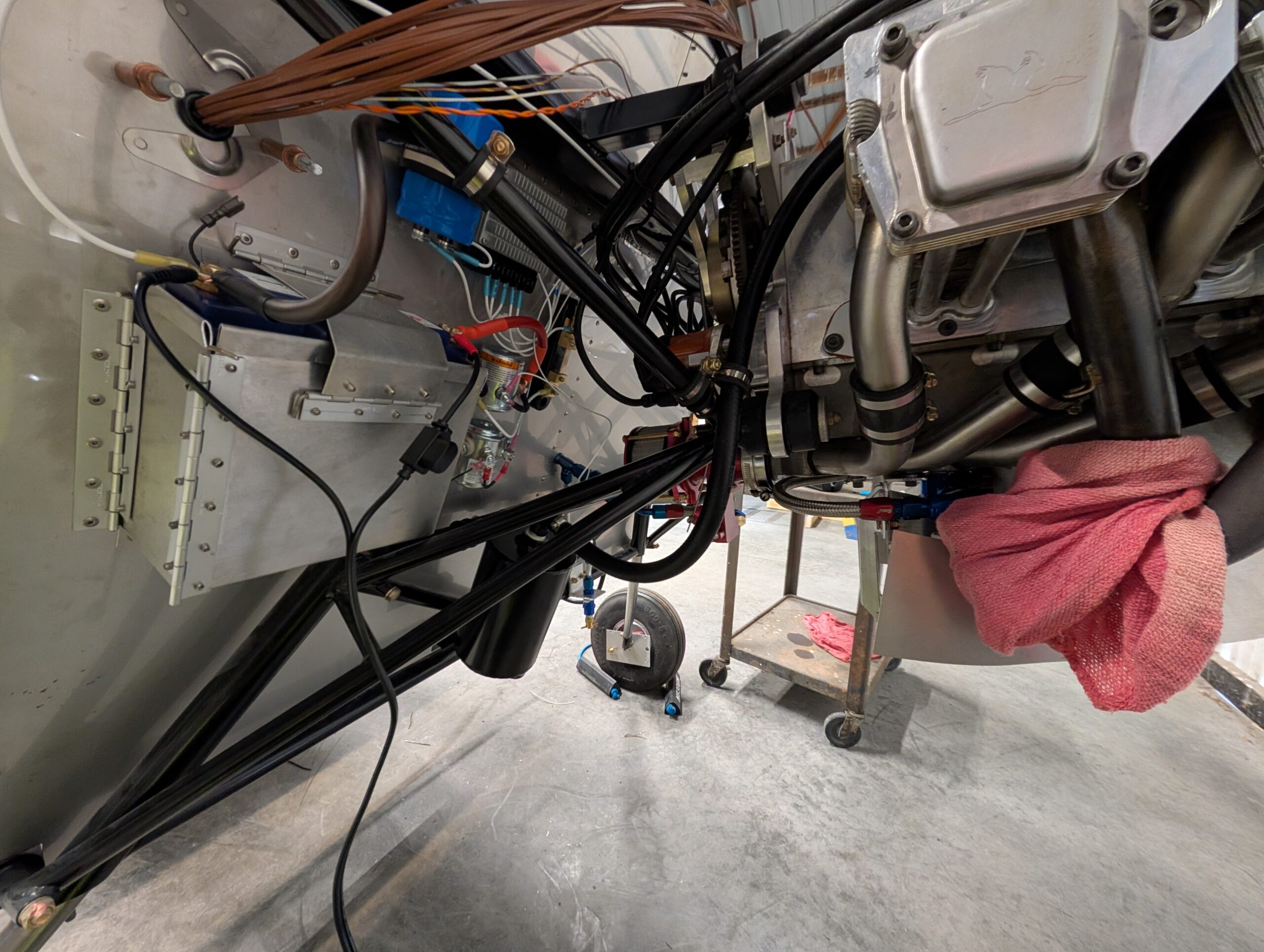
Oil Cooler and Separator Installation
Mounted oil cooler bracket onto bottom side of intake and secured bolts with Loctite 242. Temporarily mounted oil cooler to engine then marked areas of baffling to remove for block heater and oil drain. Installed AN fittings into top of oil cooler. Made oil cooler hoses and routed them from oil filter housing to oil…
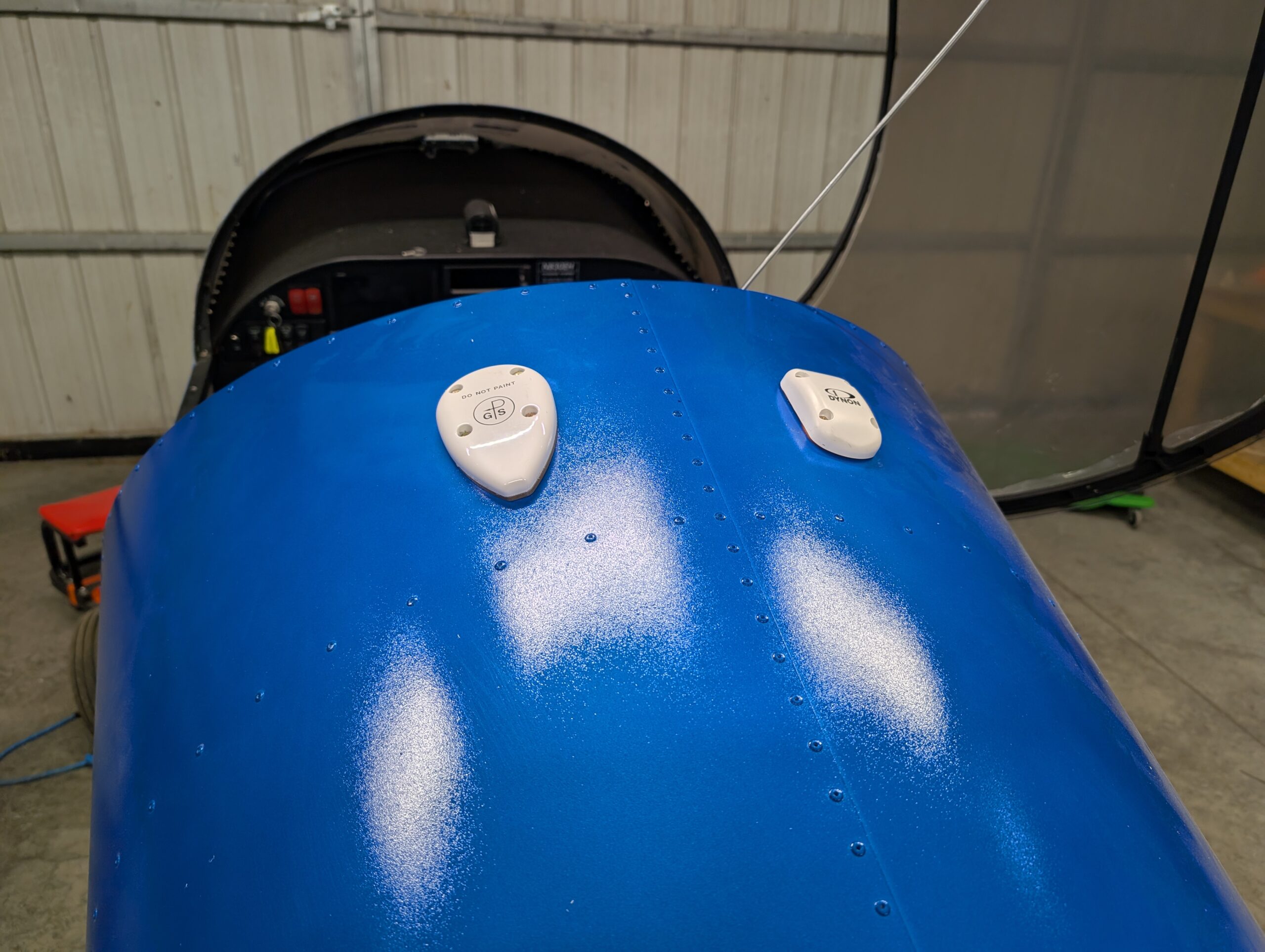
GPS Antenna Install
Drilled mounting holes for both GPS units on top of turtle deck and installed antennas using MS24693 screws. Applied clear silicone sealant around edges of GA 35 antenna to prevent water intrusion into baggage compartment; did not use sealant under Dynon antenna because a gasket was included. Secured wiring for SV-GPS-250 antenna. Hours Worked: 0.83
Mixture Cable Install
Installed mixture cable into center panel section and routed cable through previously installed cable safe. Measured out approximate length and removed inner cable from jacket (making sure to carefully catch ball in cable mechanism). Trimmed outer jacket then upsized cable hole in AeroInjector to 1/4″. Installed AeroInjector back onto back side of motor and ran…
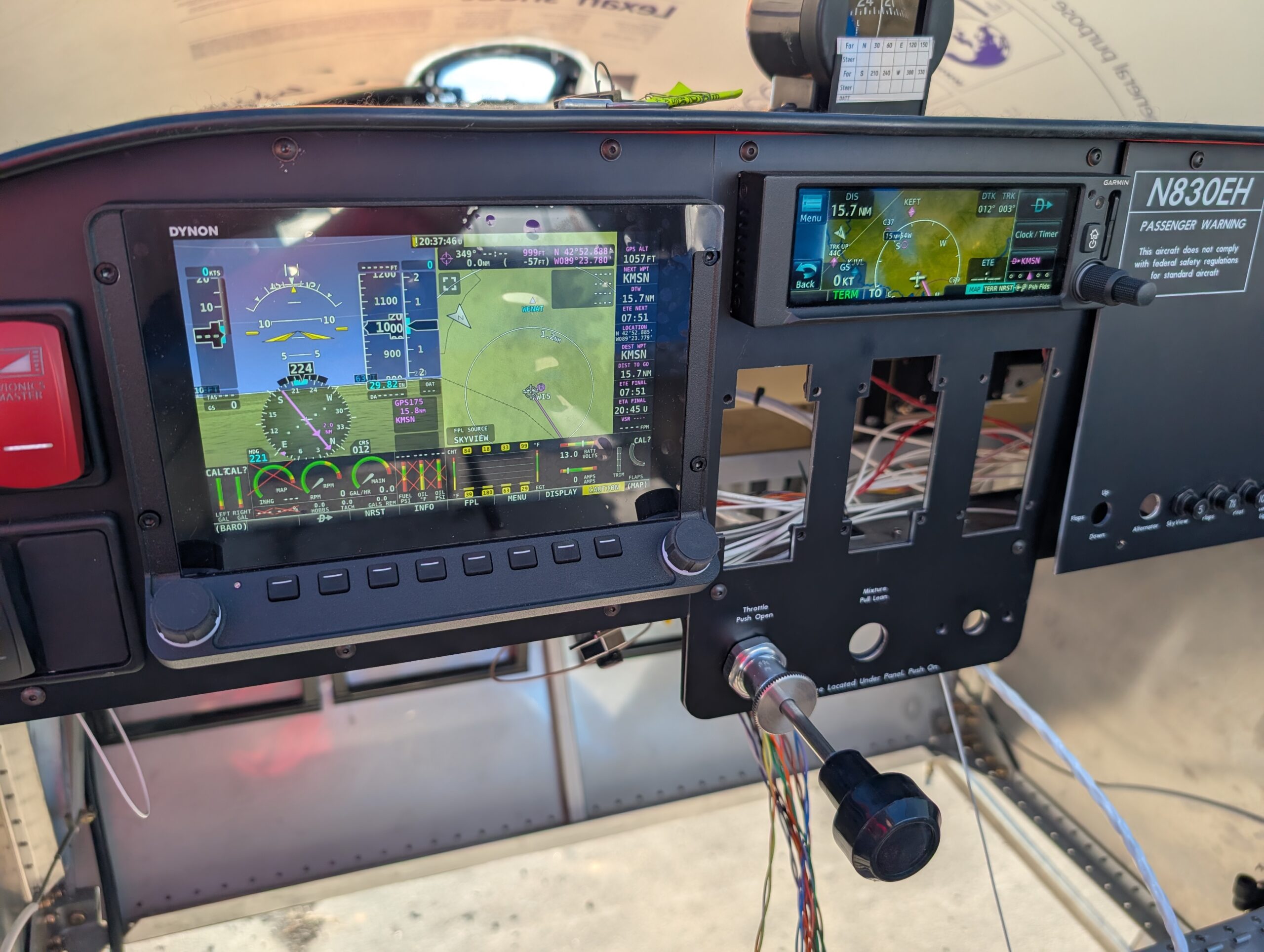
Garmin GPS 175 Install
Diagnosed GPS175 screen issue by dissassembling unit and cleaning and reseating screen ribbon connectors; ops check good. Installed GPS harness onto back of tray and wired up ground and power connections. Installed unit and tested; ops check good. Fabricated antenna cable from RG400 coax and drilled center holes for both Dynon and Garmin GPS antennas.…
GPS 175 Harness Wiring
Created Garmin GPS 175 and Dynon SV-ARINC-429 harness by cutting wires to length and installing high density Garmin pins on one side and standard density D-sub pins on the other end. Referenced the wiring diagram and Dynon’s 3rd party connection guide to fabricate harness. Opted to use common rail on the Garmin connector for ARINC…