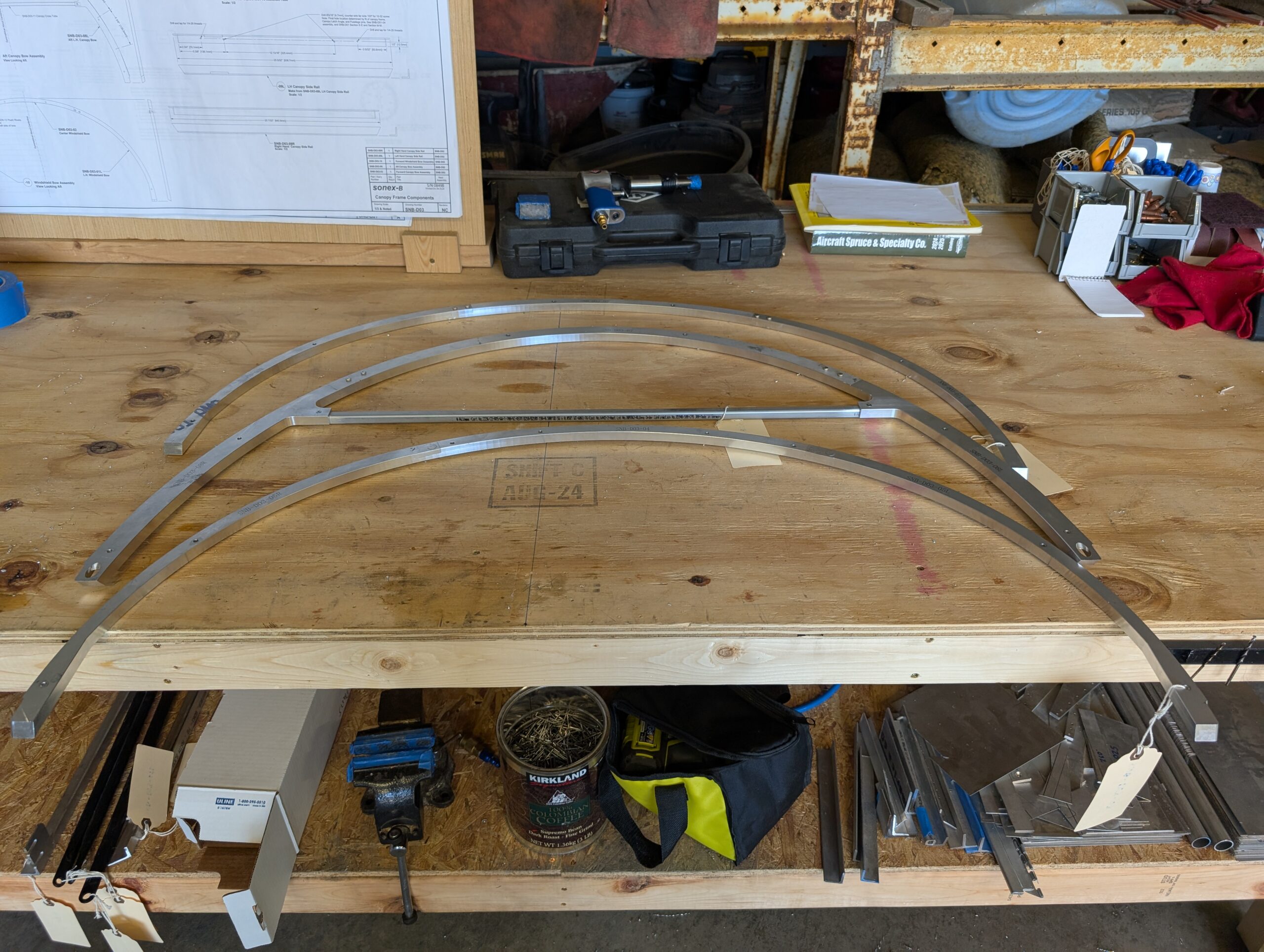
Canopy Components – Part 1
Began canopy/windshield frame prep by working on canopy forward aft bows and windshield bow. For canopy bows, started by countersinking bow holes for -6 flush rivets. Riveted components together using -6 solid rivets. Laid out bows on workbench and marked…
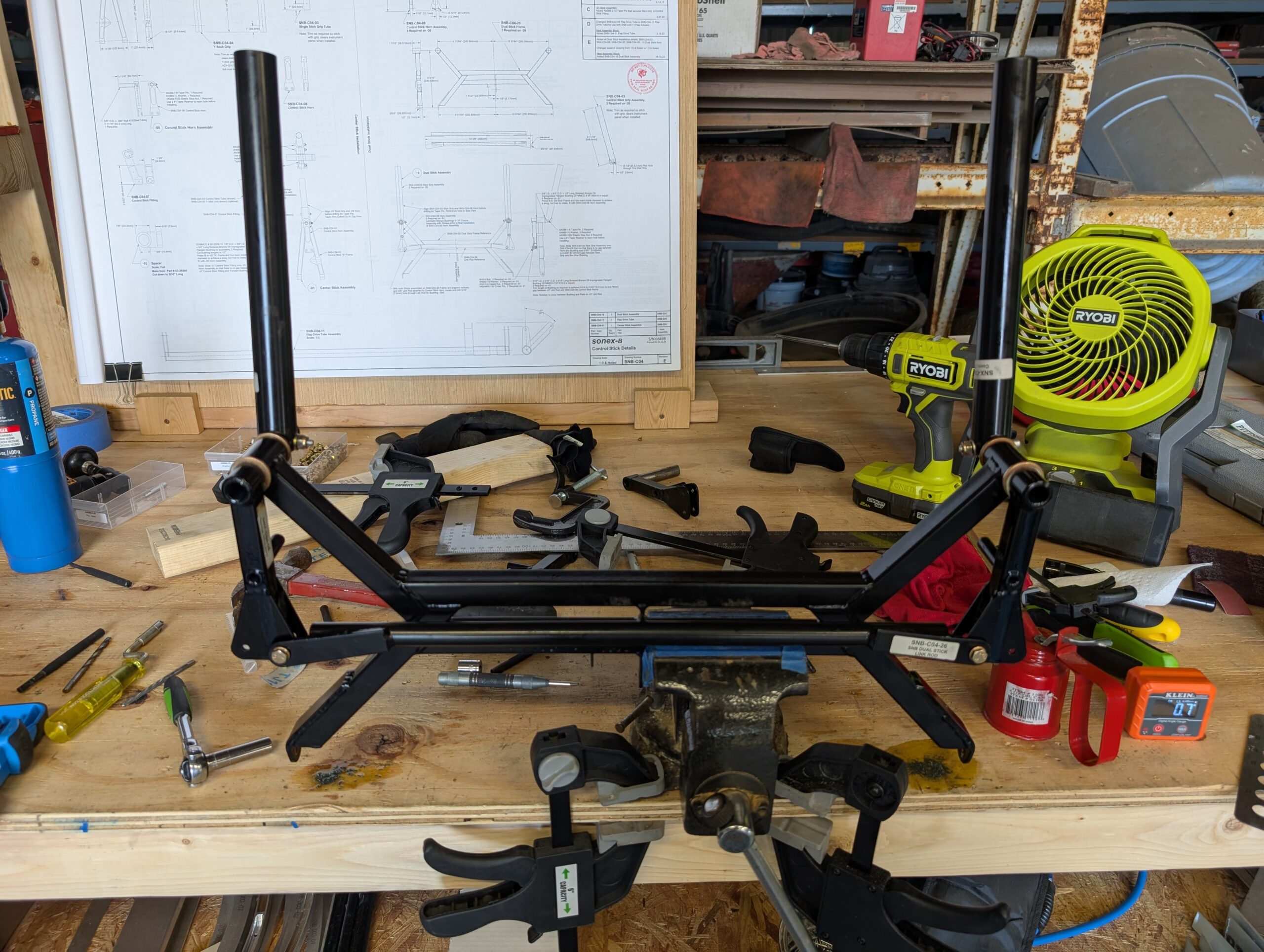
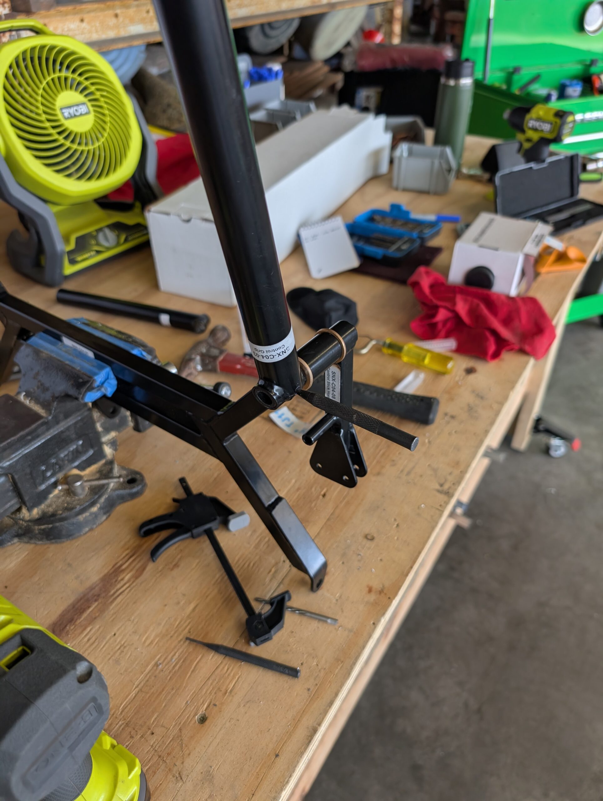
Control Stick Assembly – Part 2
Set bushings into top of control stick frame with Loctite 638. Using new taper reamer, reamed LH stick grip hole and inserted taper pin. Repeated whole process for right hand stick grip and found that sticks were not parallel with…

Control Stick Assembly – Part 1
Began control stick assembly process by drilling 1/8″ pilot holes in bottom of stick grips. Removed powder coating from shaft of control stick horns by using heat, sandpaper, and scotchbrite wheel. Installed SF-2024-8 bushings into control stick frame; fit is…
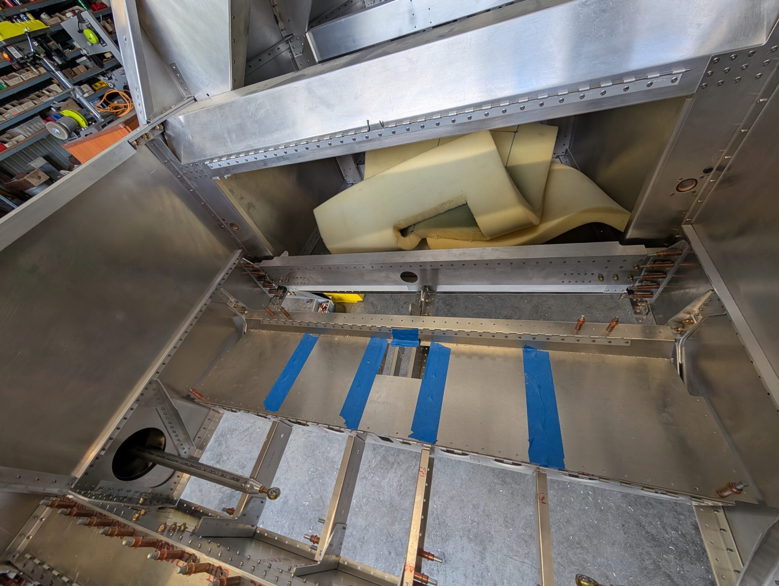
Fuselage Final Riveting – Part 1
Drilled holes through spar bumpers then riveted to fuselage with spars in place. Clecoed fuselage floor into place to check fitment with all holes aligning. Transferred pilot holes from floor into bottom of forward spar tunnel assembly then updrilled to…
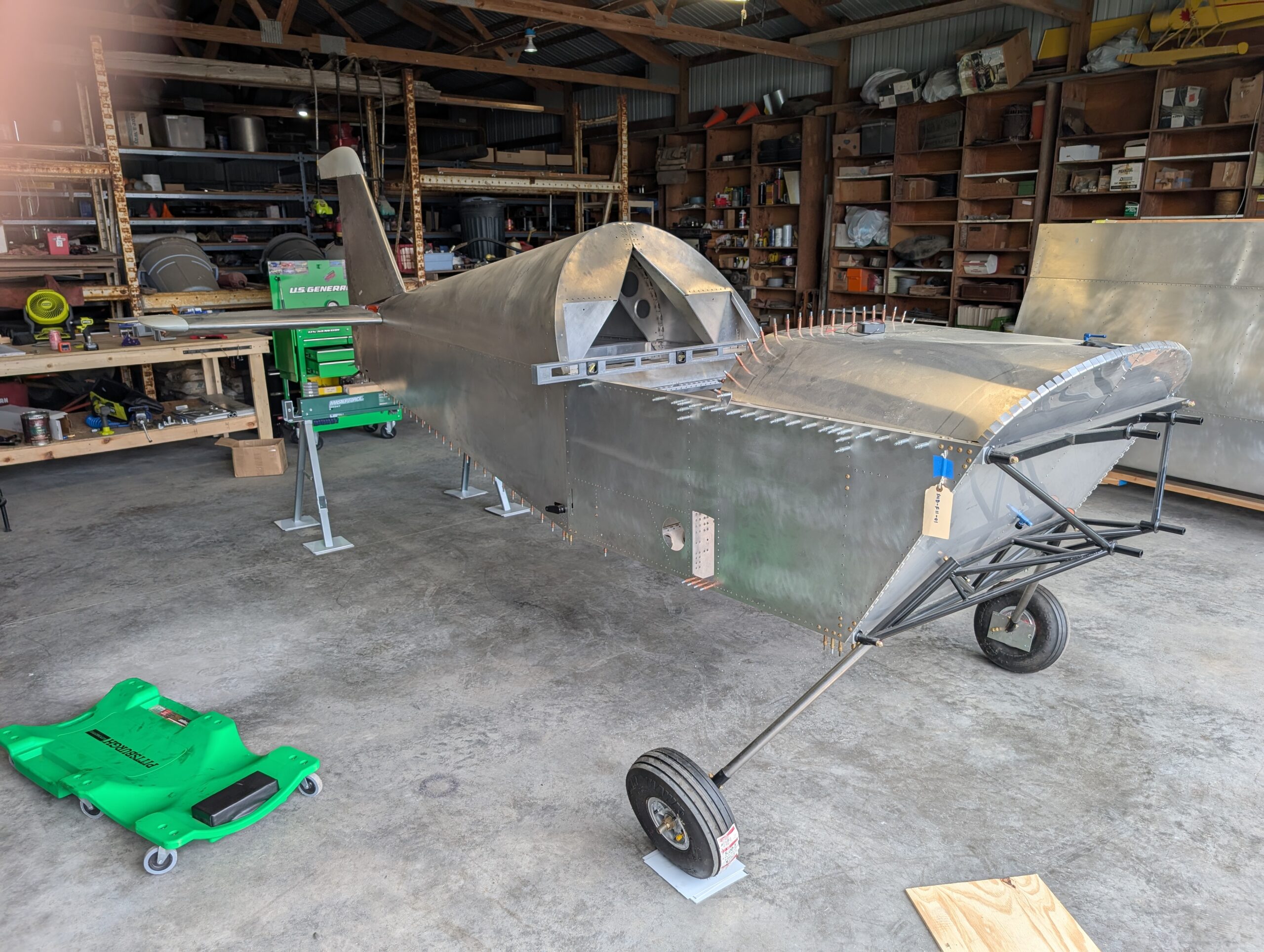
Wing Rigging – Part 4
Removed rear spar carry through from fuselage then updrilled attach angle holes through fuselage. Removed attach angles from fuselage then deburred rear spar carry through, shear web, and attach angles. Finished riveting rear spar carry through then riveted shear web…
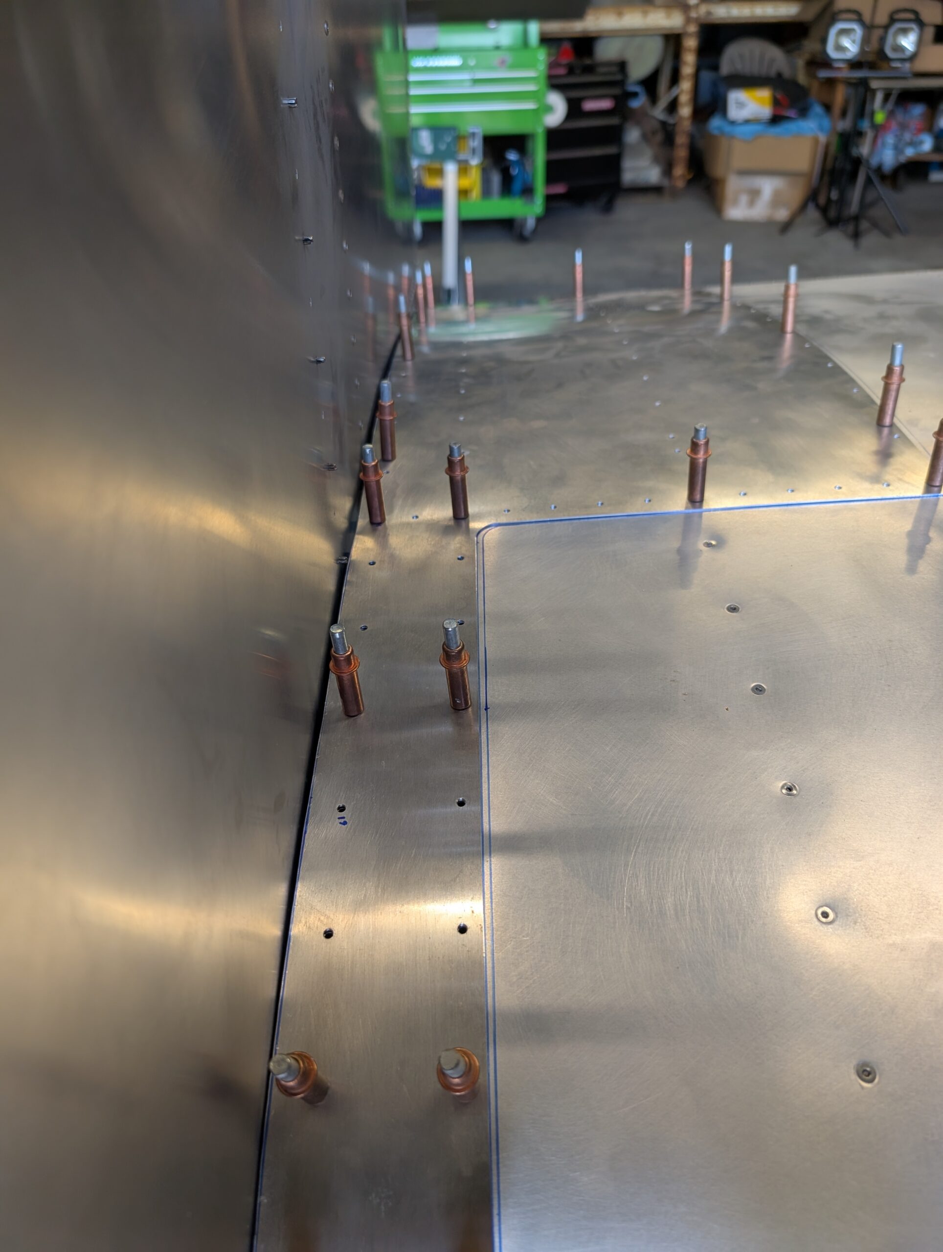
Wing Root Doublers – Part 2
Measured wing root doubler trim distances off of wing skin at each rivet hole and transferred measurements onto inside edge of wing root doublers. Trimmed excess material off with snips then deburred edges. Clecoed wing root doublers onto wing and…
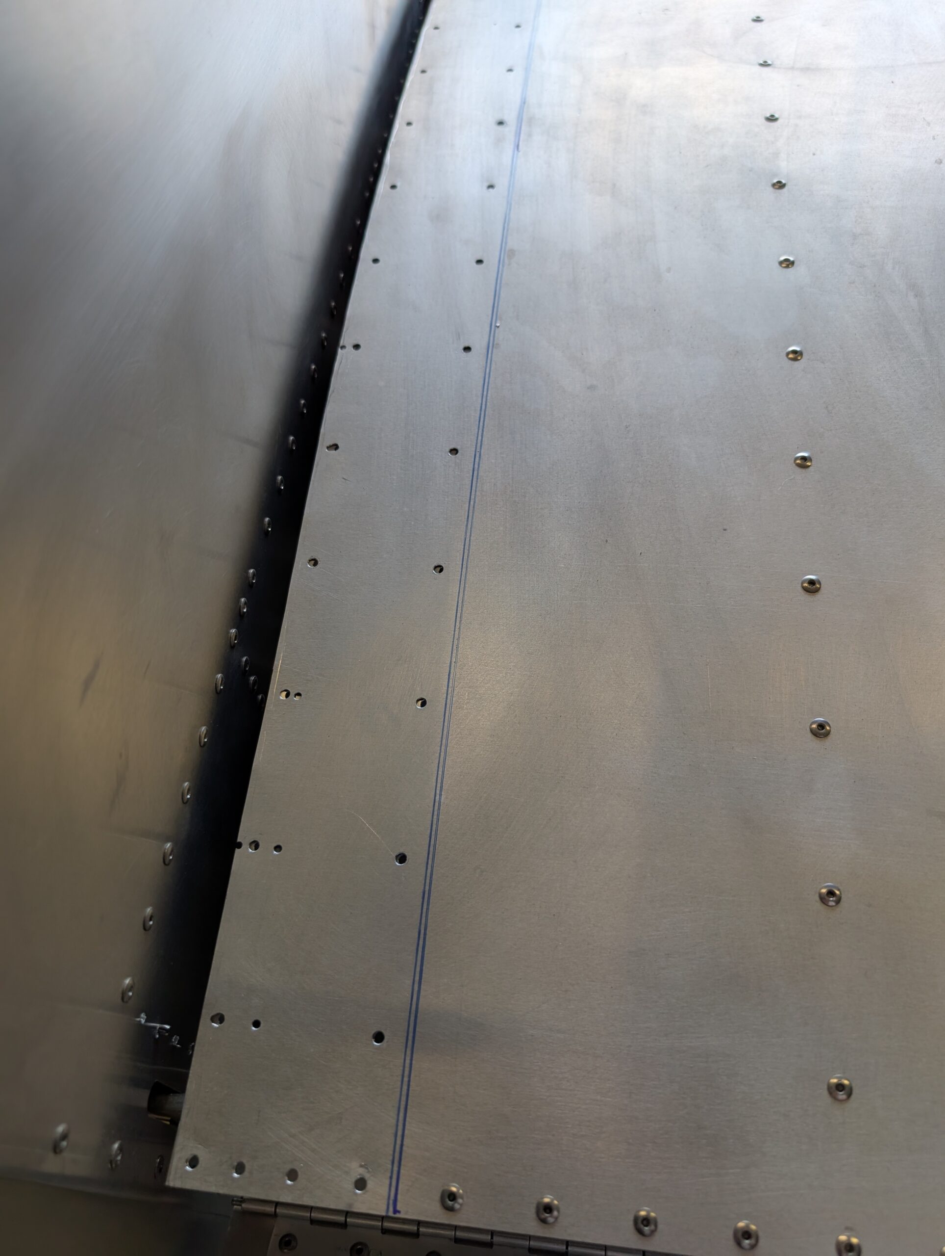
Wing Root Doublers – Part 1
Slid wings out from fuselage (one at a time) and reinstalled wing root doublers with clecoes. Marked current edge of doublers onto wing skins with sharpie. Removed doublers then slid wings back into spar tunnel and pinned into proper place.…
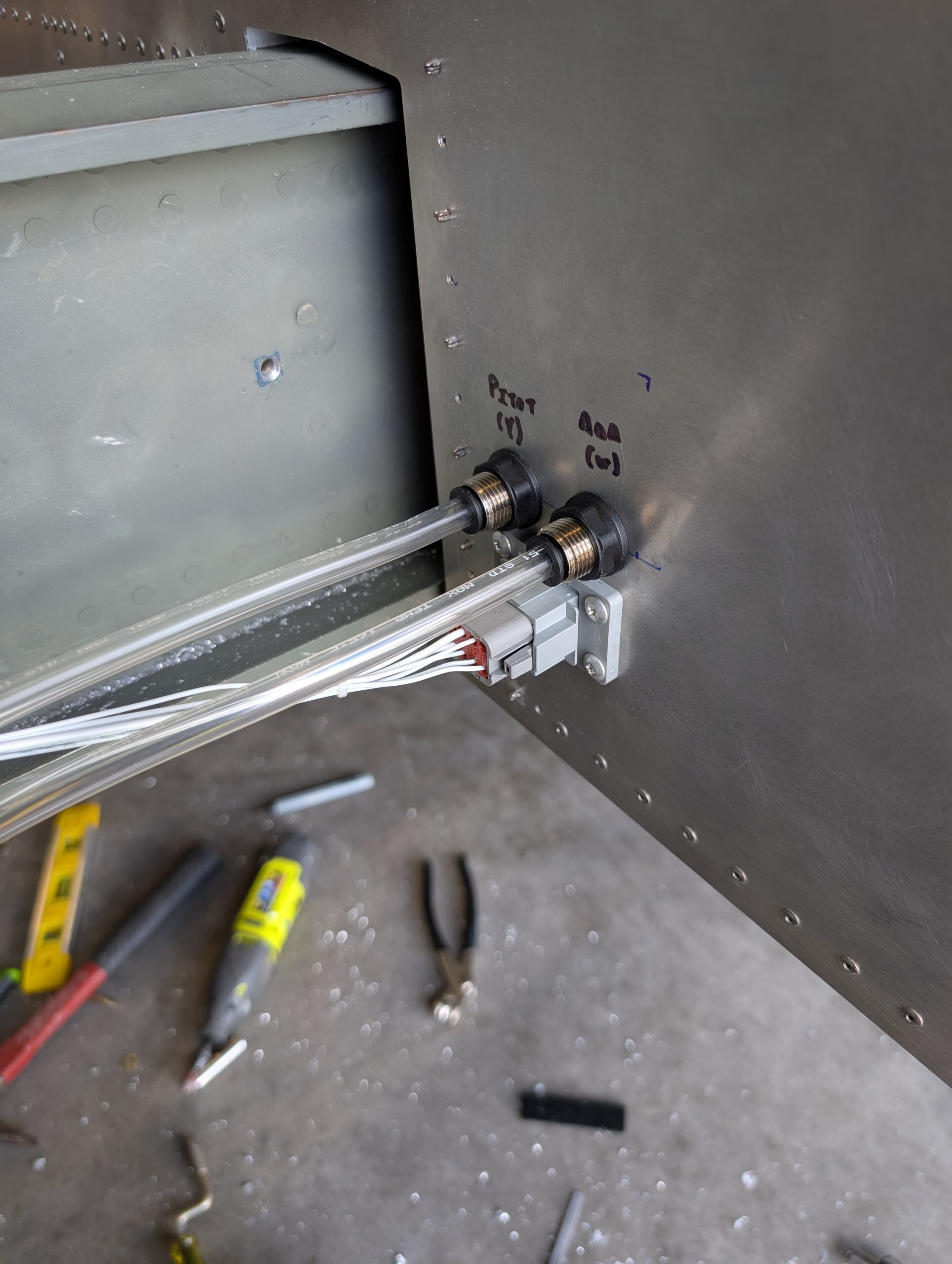
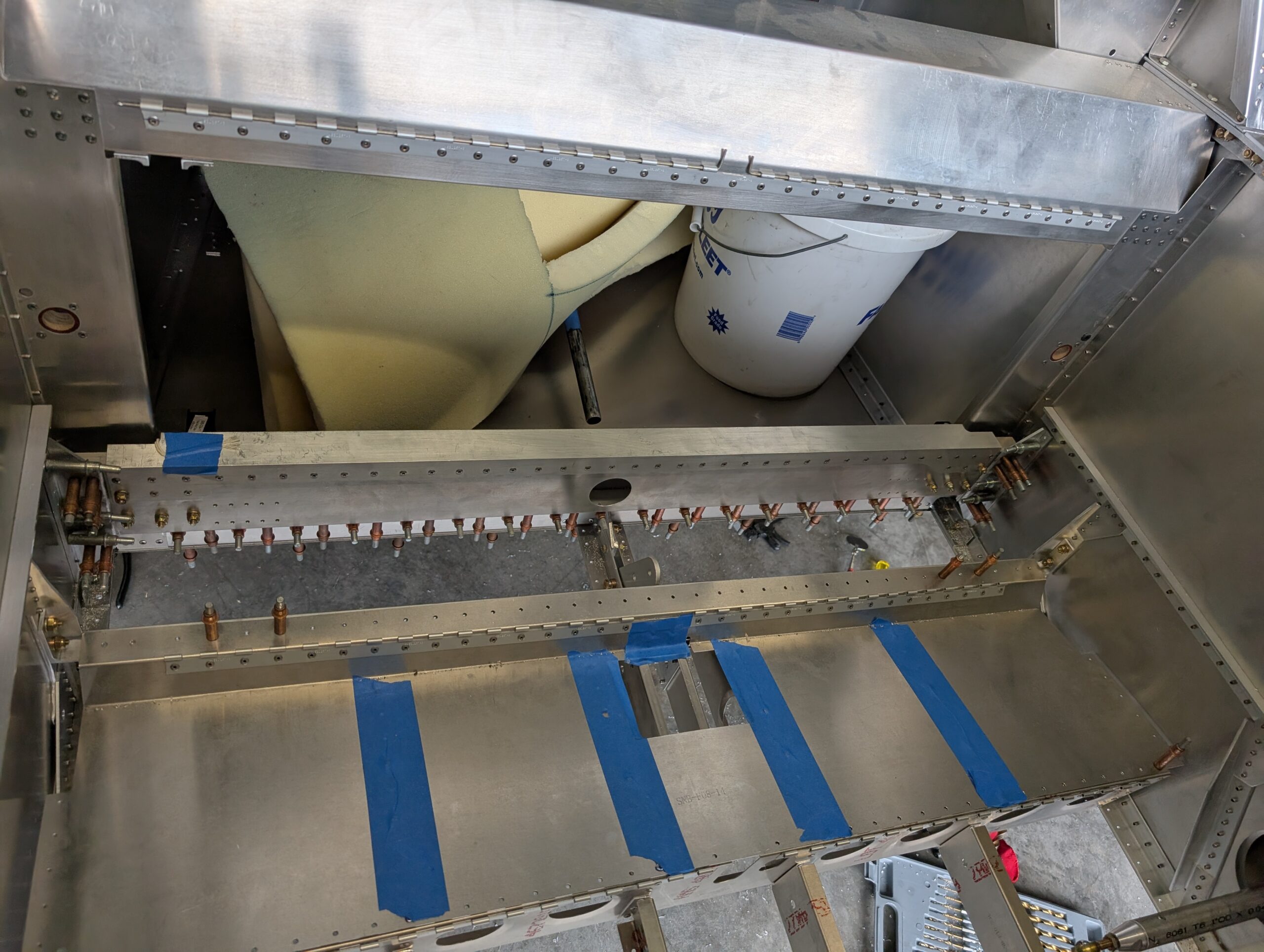
Wing Root Electrical Connectors
Removed rigging hardware from main wing spars through the three center holes in the spar webs. Slid RH wing out slightly for better access to fuselage side. Located wing root electrical connector and cut out hole for pass through. Drilled…
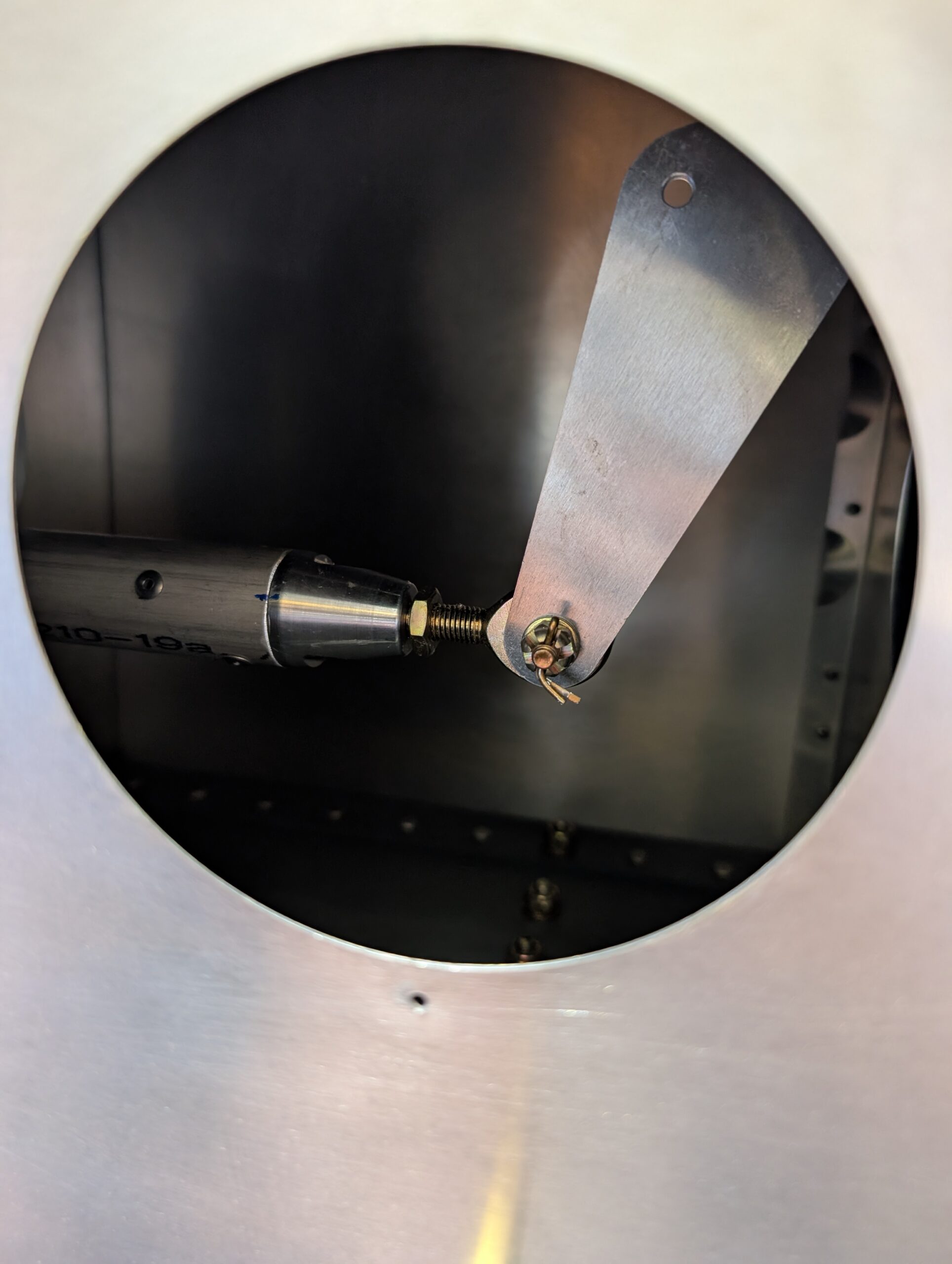
Wing Rigging – Part 3
Finished drilling main wing attach holes by using drill guide to drill 3/8″ holes in forward wing attach angles (from back to front) then updrilling each side to 1/2″. Wing pins fit it snug and wings do not wiggle on…
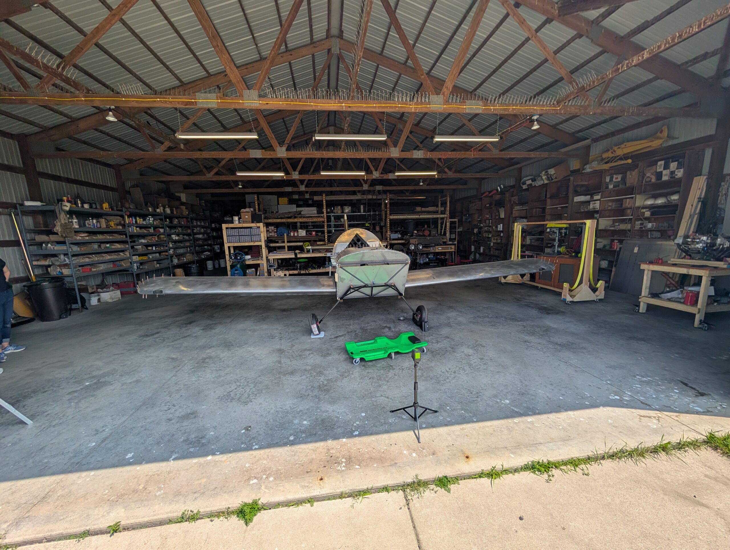
Wing Rigging – Part 2
Began wing rigging process by inserting RH wing into spar box then inserting LH wing. Supported wing tips with saw horses while trying to align the three rigging holes between the two spars. Process went much easier with three people:…
Wing Pushrod Installation – Part 1
Removed aileron bellcrank access covers from wings and inserted C03-01 main aileron pushrods into wings. Attached to aileron bellcrank with AN3 hardware and castle nut. Installed C03-03 flap pushrods onto flaps with AN4 hardware. Hours Worked: 0.98
Wing Rigging – Part 1
Removed forward tunnel zee and forward wing attach angles from fuselage. Updrilled alignment holes in forward and aft spar tunnels to 5/8″ to facilitate rigging bolts. Removed wing root doubelers from wings in preparation for wing rigging procedure. Began process…