Electrical
-
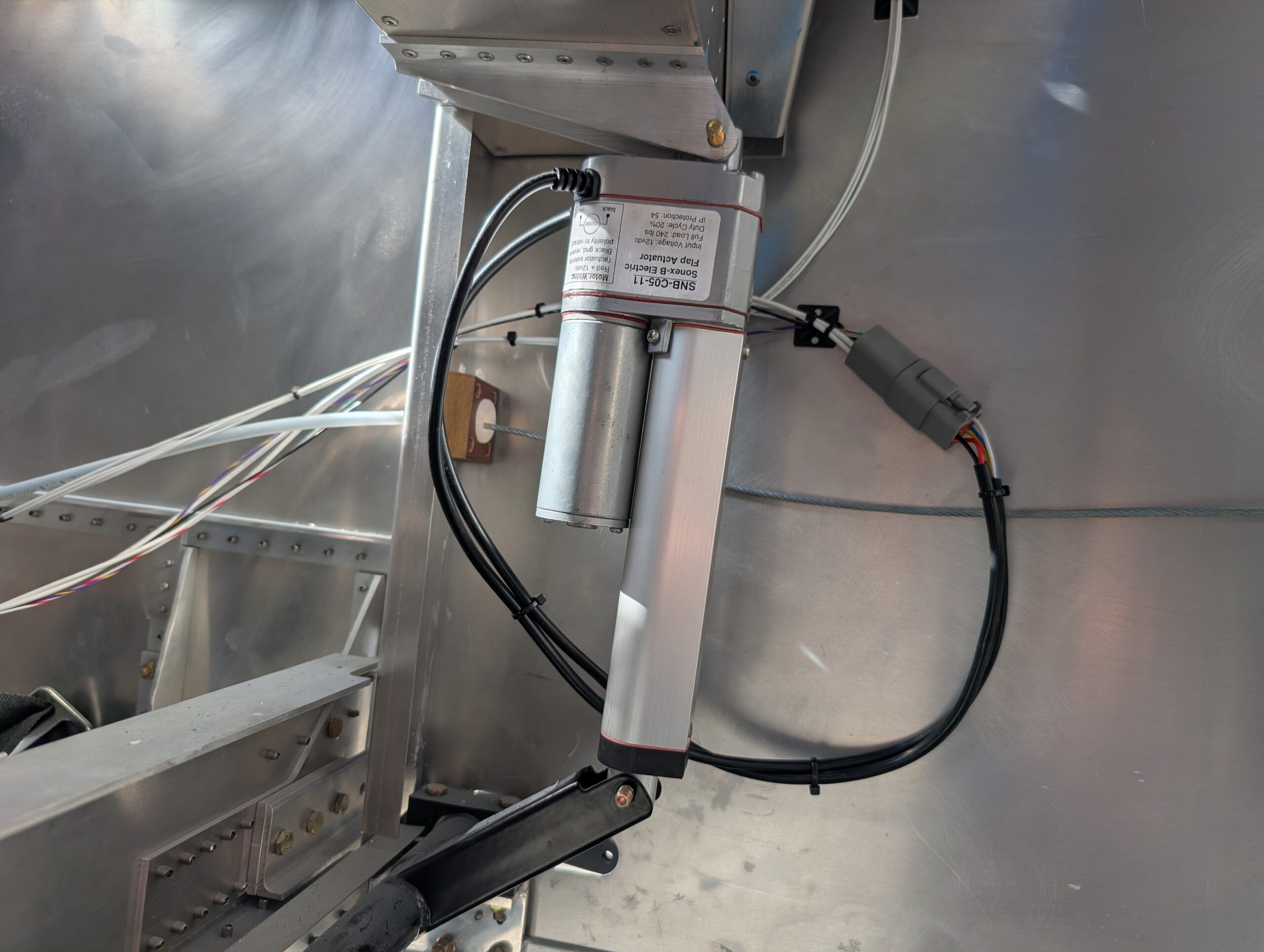
Flap Motor Wiring
Partially wired flap switch on bench and added extra leads to make installation into panel easier. Installed flap switch into panel and connected ground and power wires. Decided to share ground with alternator reset switch so ran additional wire to reset switch. Used Molex connector for reset switch which contacted outside terminals at the right…
-
FWF Wiring – Part 3
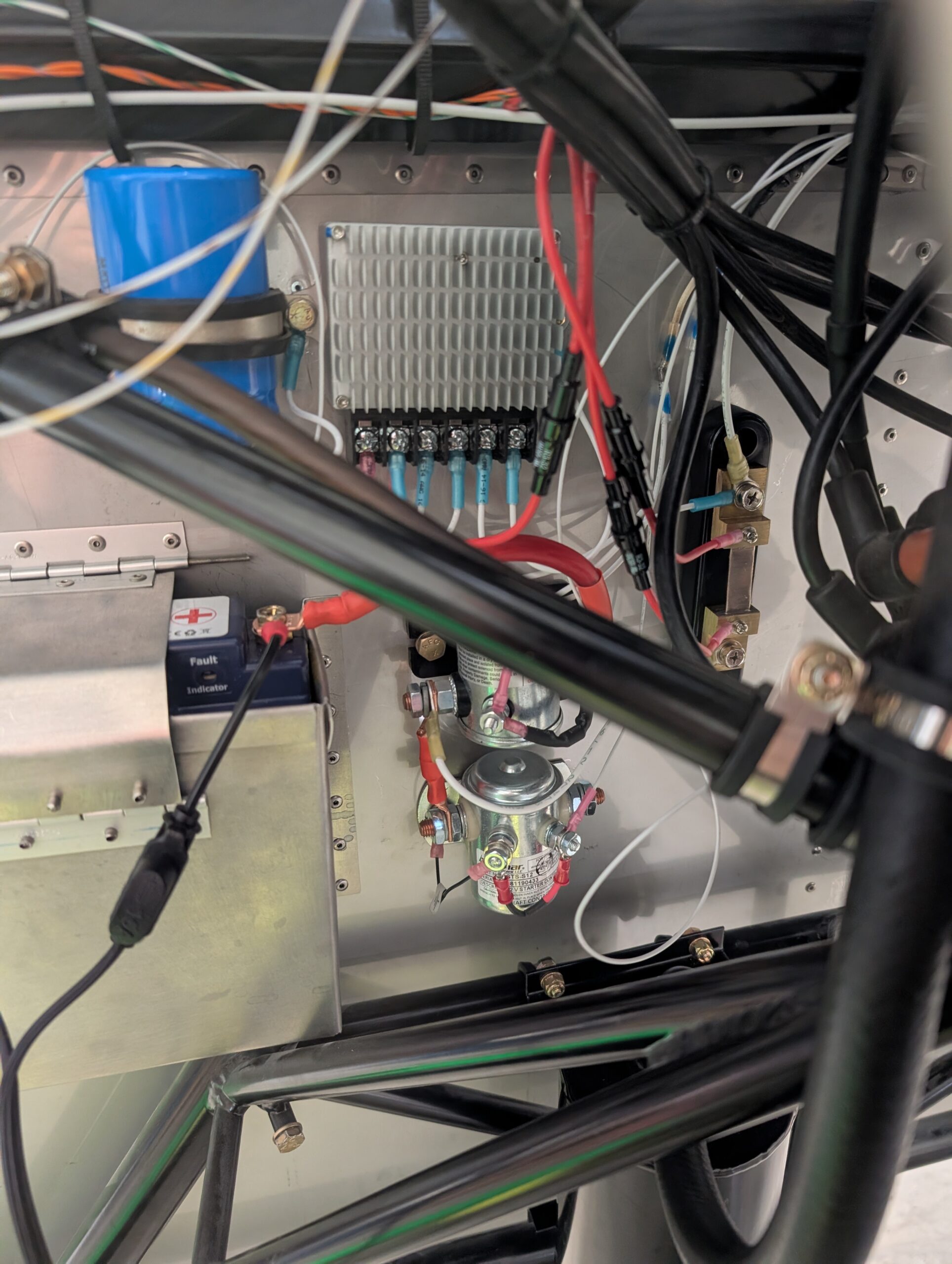
Terminated amp shunt wires and tachometer lead by installing inline fuse holders with 1 amp fuses. Ran voltage regulator reset line from panel to voltage regulator. Hours Worked: 0.89
-
GPS Antenna Install
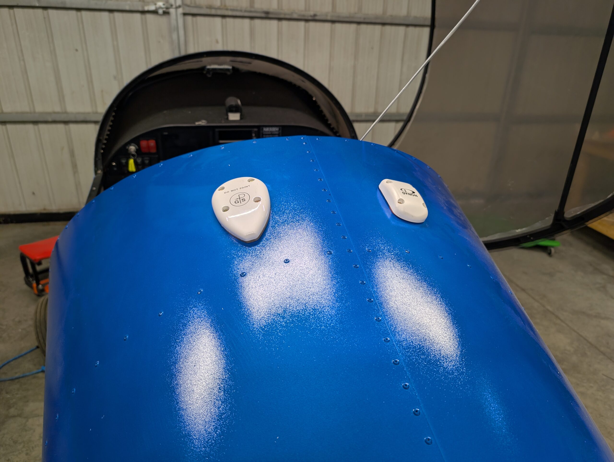
Drilled mounting holes for both GPS units on top of turtle deck and installed antennas using MS24693 screws. Applied clear silicone sealant around edges of GA 35 antenna to prevent water intrusion into baggage compartment; did not use sealant under Dynon antenna because a gasket was included. Secured wiring for SV-GPS-250 antenna. Hours Worked: 0.83
-
Garmin GPS 175 Install
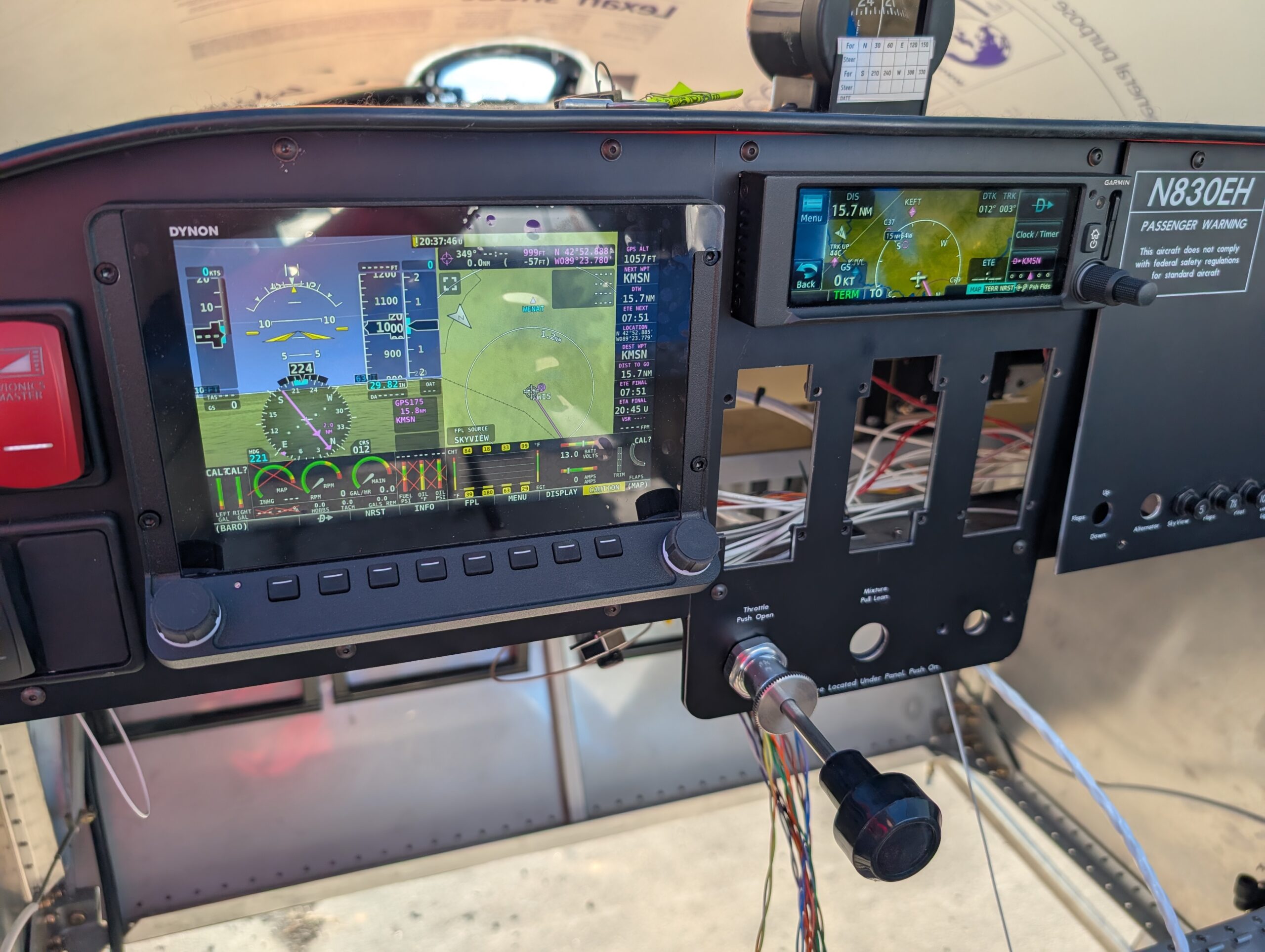
Diagnosed GPS175 screen issue by dissassembling unit and cleaning and reseating screen ribbon connectors; ops check good. Installed GPS harness onto back of tray and wired up ground and power connections. Installed unit and tested; ops check good. Fabricated antenna cable from RG400 coax and drilled center holes for both Dynon and Garmin GPS antennas.…
-

GPS 175 Harness Wiring
Created Garmin GPS 175 and Dynon SV-ARINC-429 harness by cutting wires to length and installing high density Garmin pins on one side and standard density D-sub pins on the other end. Referenced the wiring diagram and Dynon’s 3rd party connection guide to fabricate harness. Opted to use common rail on the Garmin connector for ARINC…
-
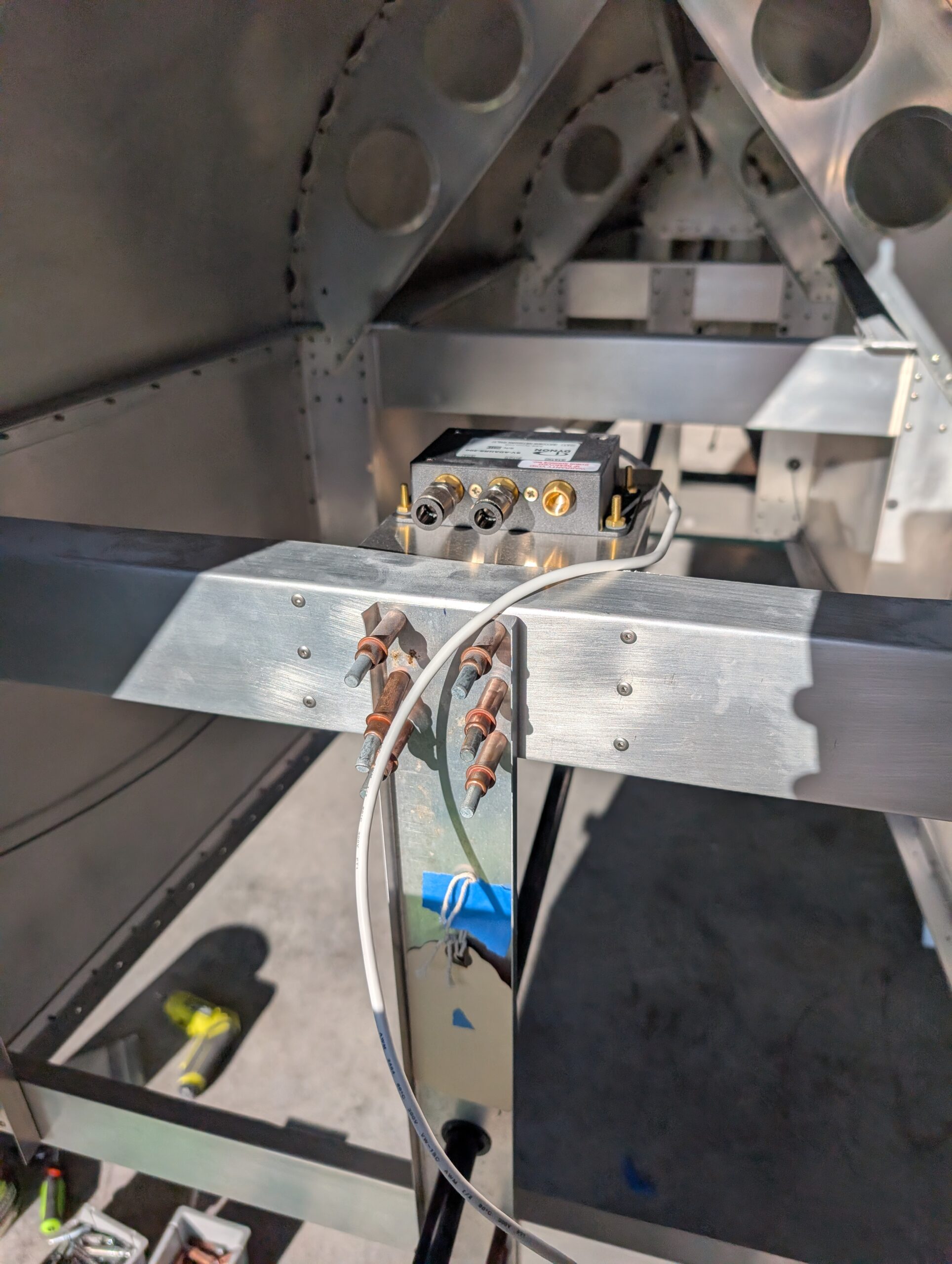
AHRS Unit Shelf
Installed GPS 175 tray behind panel in preparation for GPS install. Connected SkyView WiFi adapter to back of display along with USB extension (which will be secured at a later time). Fabricated shelf for SV-ADAHRS-200 box from 0.032 sheet. Bent and cut flat template then clecoed onto back side of the #2 cross tie. Checked…
-
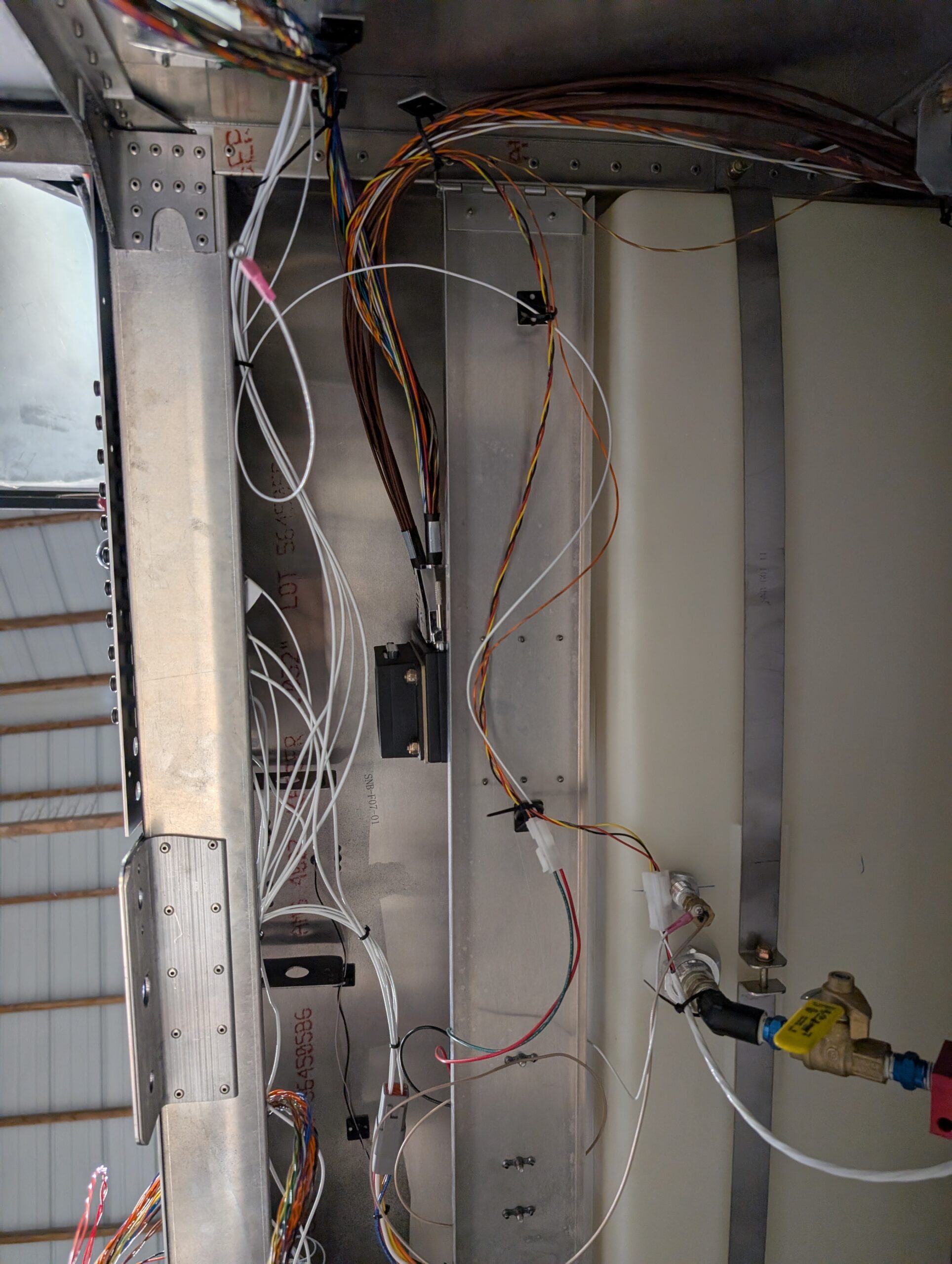
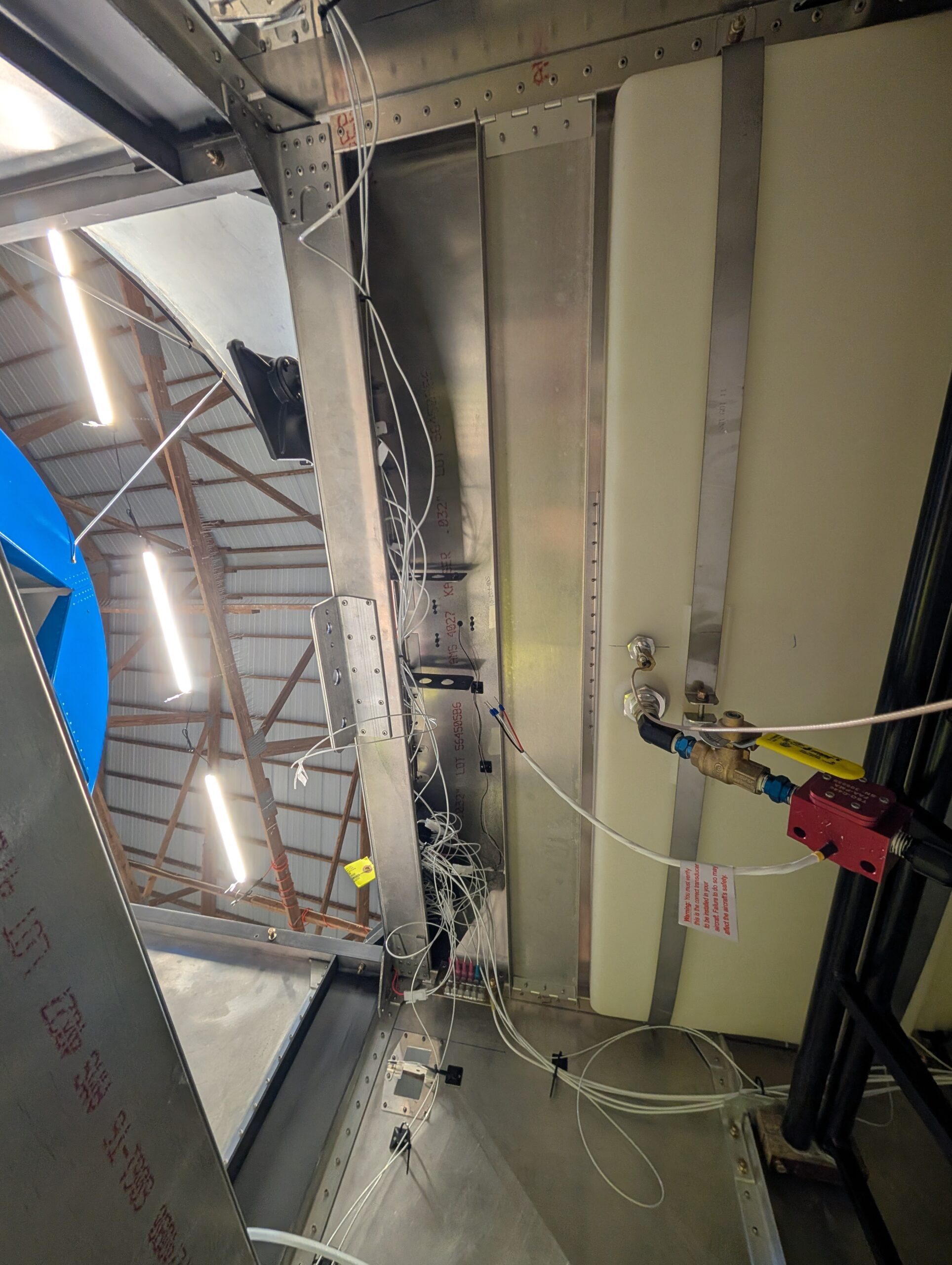
Fuel System Electronics Wiring
Installed molex connectors on fuel probe and fuel flow transducer and connected components to EMS harness and SkyView circuit breaker. Attached voltmeter input of EMS box to main bus bar. Ran firewall forward wires of EMS harness through gromet to engine compartment. Installed main display harness and hooked up power and ground connections. Connected SV-EMS-220…
-
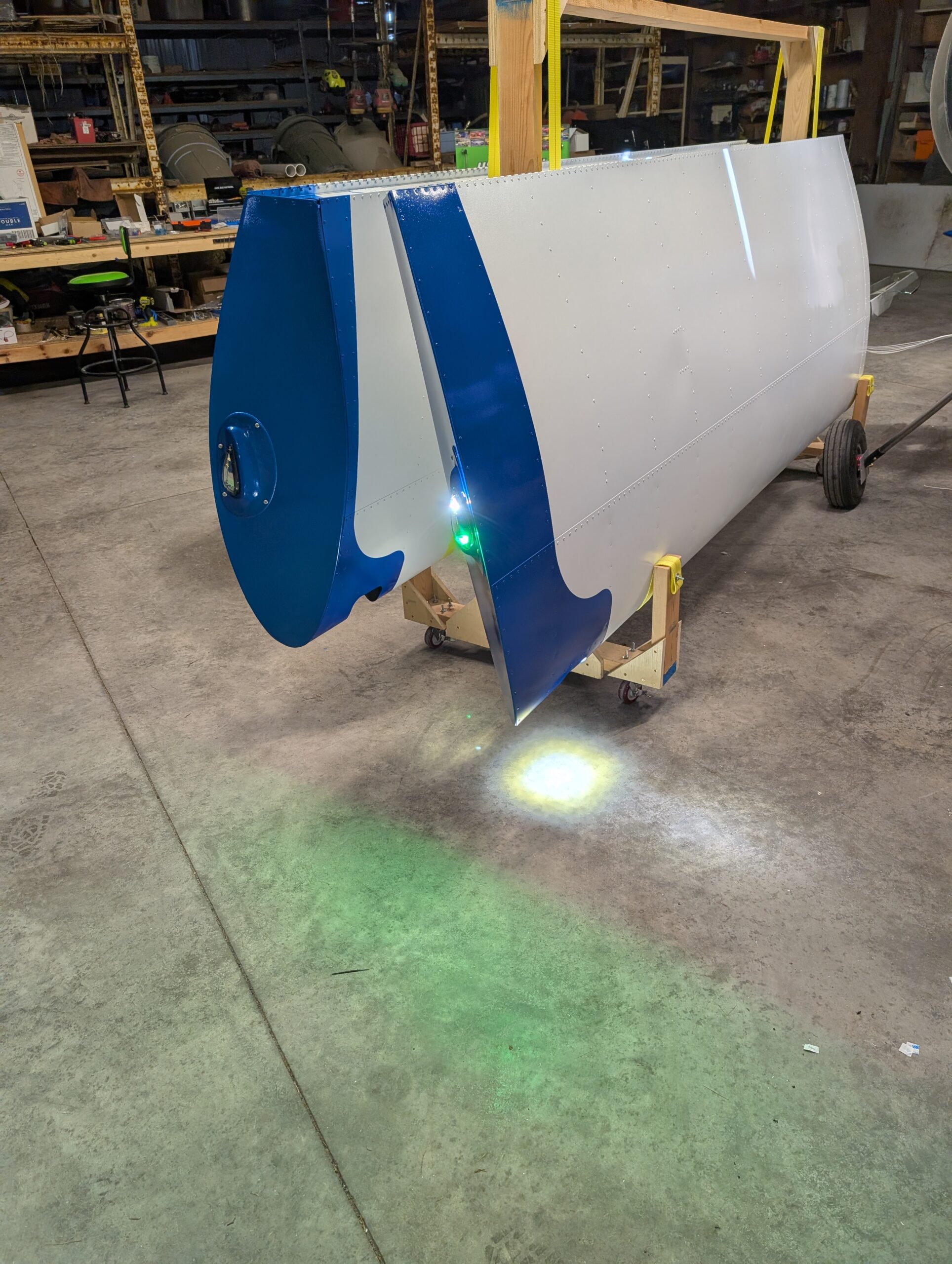
Wing Root Wiring
Attached wing tip lights to tip light fairings then installed DT connectors. Installed lights and fairings onto tips of wings. Terminated wing root wires at bulkhead connectors and tested functions. Reinstalled pneumatic bulkhead fittings for RH wing. Installed CHT/EGT harness and ran wires through firewall grommet. Installed engine sensor harness as well. Hours Worked: 2.87
-
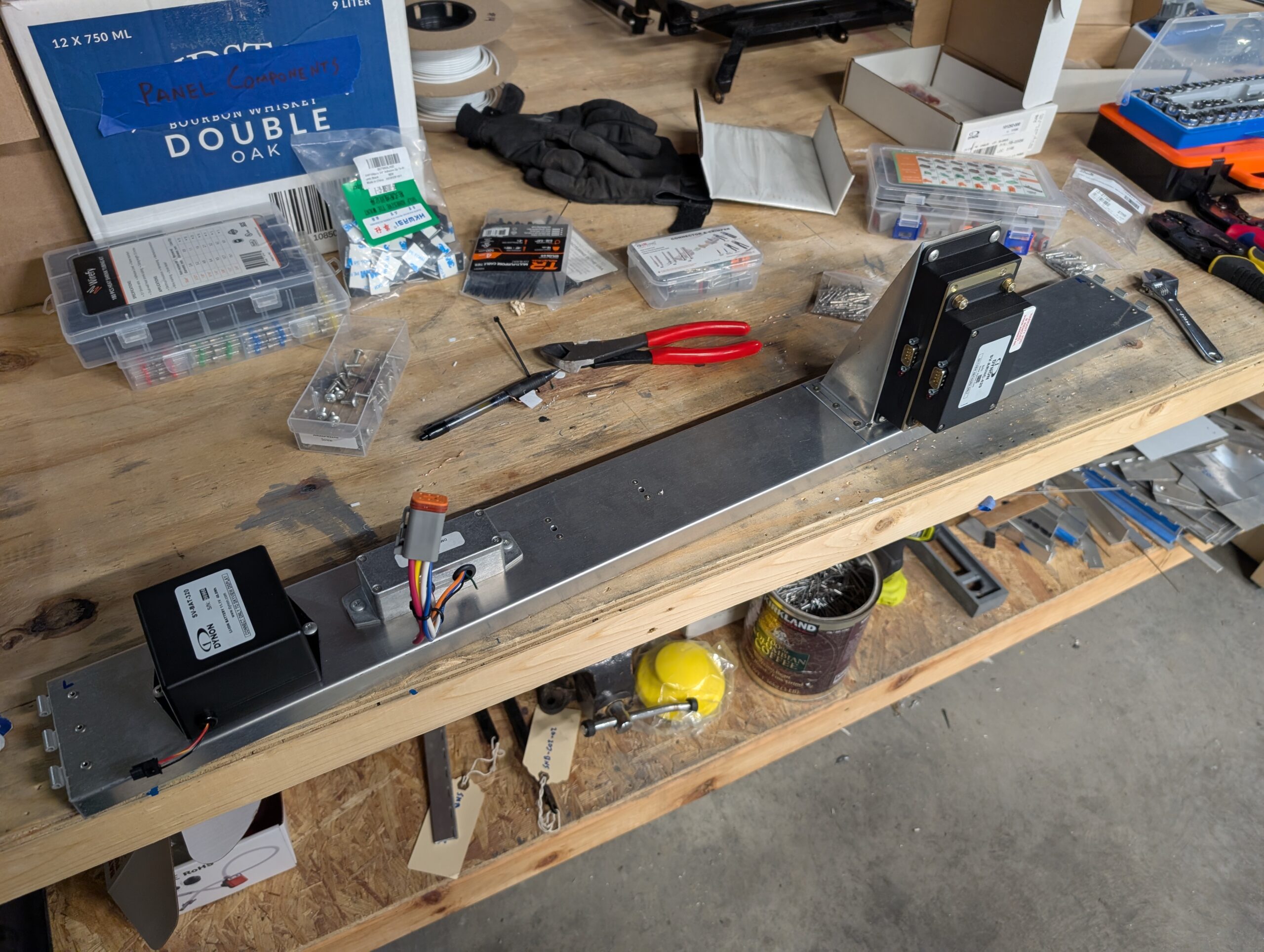
Avionics Sub-panel – Part 2
Created mount angle for EMS and ARINC module from scrap 0.032 sheet due to lack of clearance for modules with connectors on both ends. Riveted nut plates to vertical mount and then riveted mount to avionics shelf. Laid out backup battery, wig wag module, and fuel probe box onto shelf and marked mounting holes. Installed…
-
Avionics Sub-panel – Part 1
Created avionics sub-panel (shelf) from Z04-03 stock. Made mounting hinge pieces from -5 piano hinge to allow for more adjustability. Mocked up shelf locating behind panel and in front of fuel tank and pilot drilled hinges to upper longerons then to shelf. Removed assembly, updrilled hinge halves, then riveted hinge mounts to upper longerons. Riveted…
-
Circuit Breaker Wiring – Part 1
Began terminating panel wires to RH panel cover and circuit breakers. Connected master relay, master switch, and avionics switch wires to bus bars then connected available components to top of circuit breakers. Screwed RH panel cover into place onto panel backer. Should have enough room to attach future components with circuit breakers in place. Hours…
-
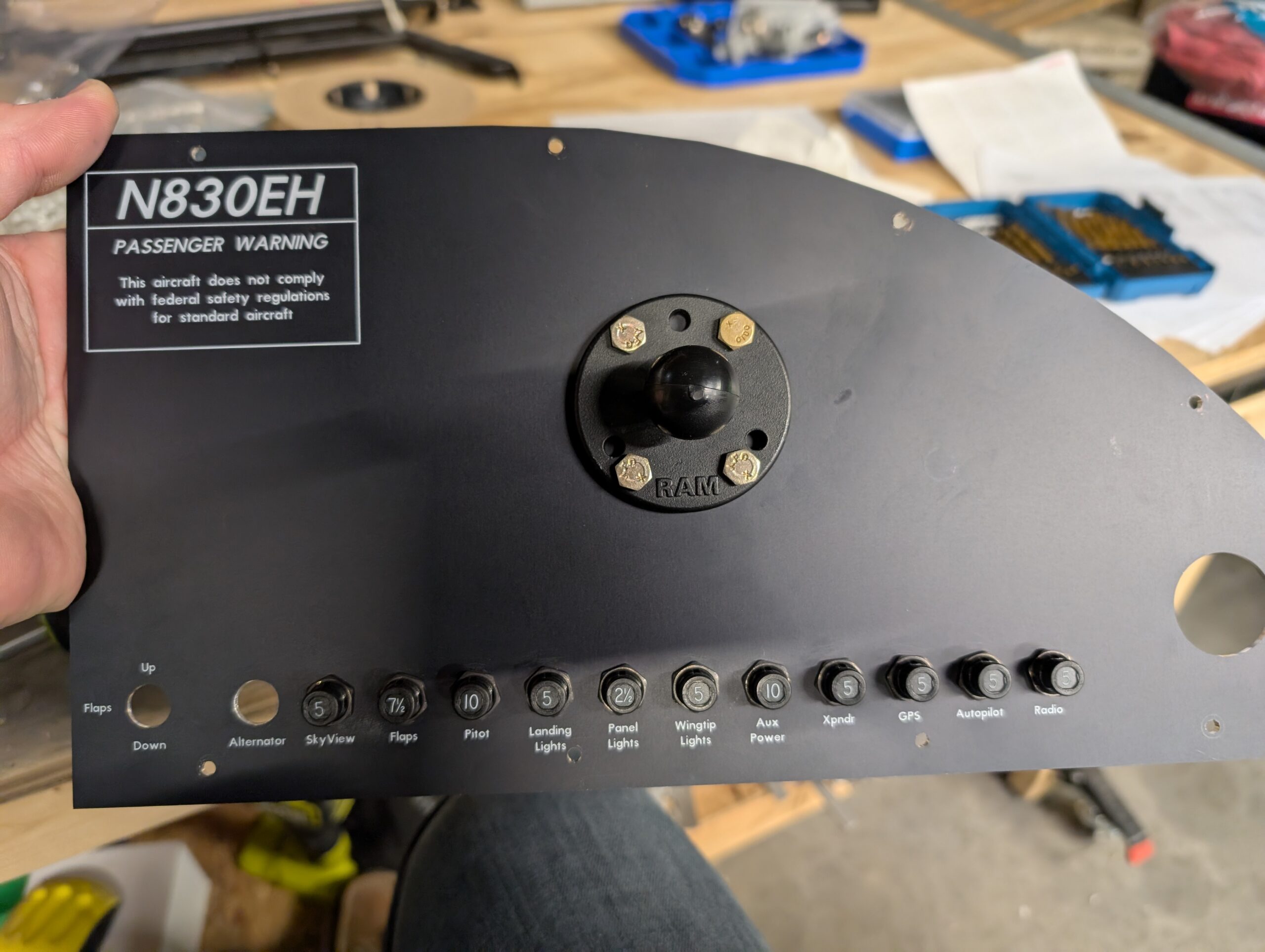
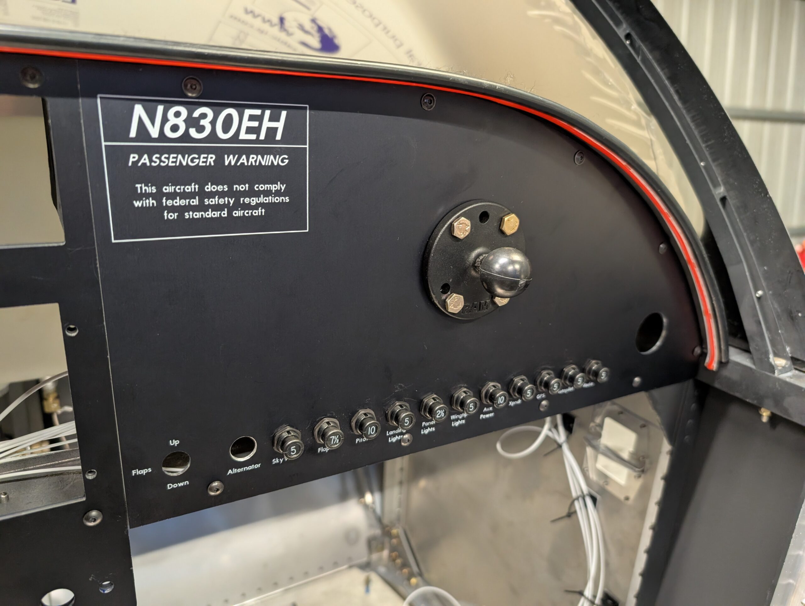
Circuit Breaker Mounting
Bolted Ram mount base to RH panel cover using AN3 hardware. Cut copper bus bars to size and drilled circuit breaker holes at 0.8 inch spacing. Installed circuit breakers into RH panel cover then secured bus bar onto bottom terminals of circuit breakers with 6R4 screws. Used two separate bus bars for circuit breakers; one…