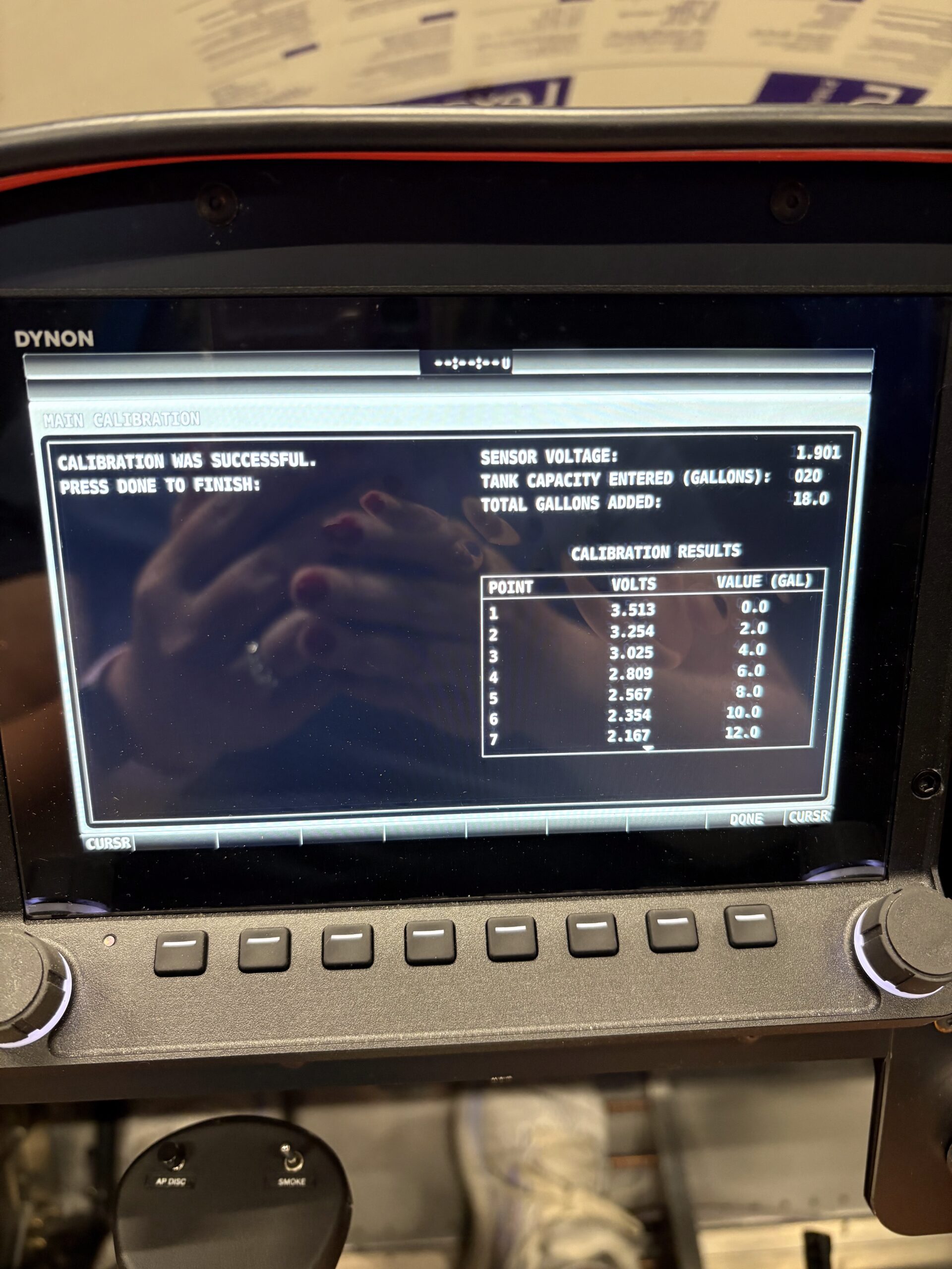
• Mixture Cable Install

    Mixture Cable Install

    |

    Installed mixture cable into center panel section and routed cable through previously installed cable safe. Measured out approximate length and removed inner cable from jacket (making sure to carefully catch ball in cable mechanism). Trimmed outer jacket then upsized cable…

    More Details…

  • Garmin GPS 175 Install

    Garmin GPS 175 Install

    |

    Diagnosed GPS175 screen issue by dissassembling unit and cleaning and reseating screen ribbon connectors; ops check good. Installed GPS harness onto back of tray and wired up ground and power connections. Installed unit and tested; ops check good. Fabricated antenna…

    More Details…

  • GPS 175 Harness Wiring

    GPS 175 Harness Wiring

    |

    Created Garmin GPS 175 and Dynon SV-ARINC-429 harness by cutting wires to length and installing high density Garmin pins on one side and standard density D-sub pins on the other end. Referenced the wiring diagram and Dynon’s 3rd party connection…

    More Details…

  • AHRS Unit Shelf

    AHRS Unit Shelf

    |

    Installed GPS 175 tray behind panel in preparation for GPS install. Connected SkyView WiFi adapter to back of display along with USB extension (which will be secured at a later time). Fabricated shelf for SV-ADAHRS-200 box from 0.032 sheet. Bent…

    More Details…

  • Throttle Bell Crank – Part 2

    Throttle Bell Crank – Part 2

    |

    Installed throttle cable in center panel area. Located throttle and mixture cable pass-through locations on firewall and prepared holes for cable bulkheads. Installed both cable safes. Located throttle bellcrank assembly based on throttle cable pass through then transferred mounting holes…

    More Details…

  • Thrust Line Measurement

    Thrust Line Measurement

    |

    Verified engine alignment before moving forward by leveling fuselage with saw horse under tail and setting up laser level though center of crank. Measured bottom front corner of fuselage at 22.75″ from floor and center of crank as 40.25″ from…

    More Details…

  • Wing Root Wiring

    Wing Root Wiring

    Attached wing tip lights to tip light fairings then installed DT connectors. Installed lights and fairings onto tips of wings. Terminated wing root wires at bulkhead connectors and tested functions. Reinstalled pneumatic bulkhead fittings for RH wing. Installed CHT/EGT harness…

    More Details…