emkrueger830

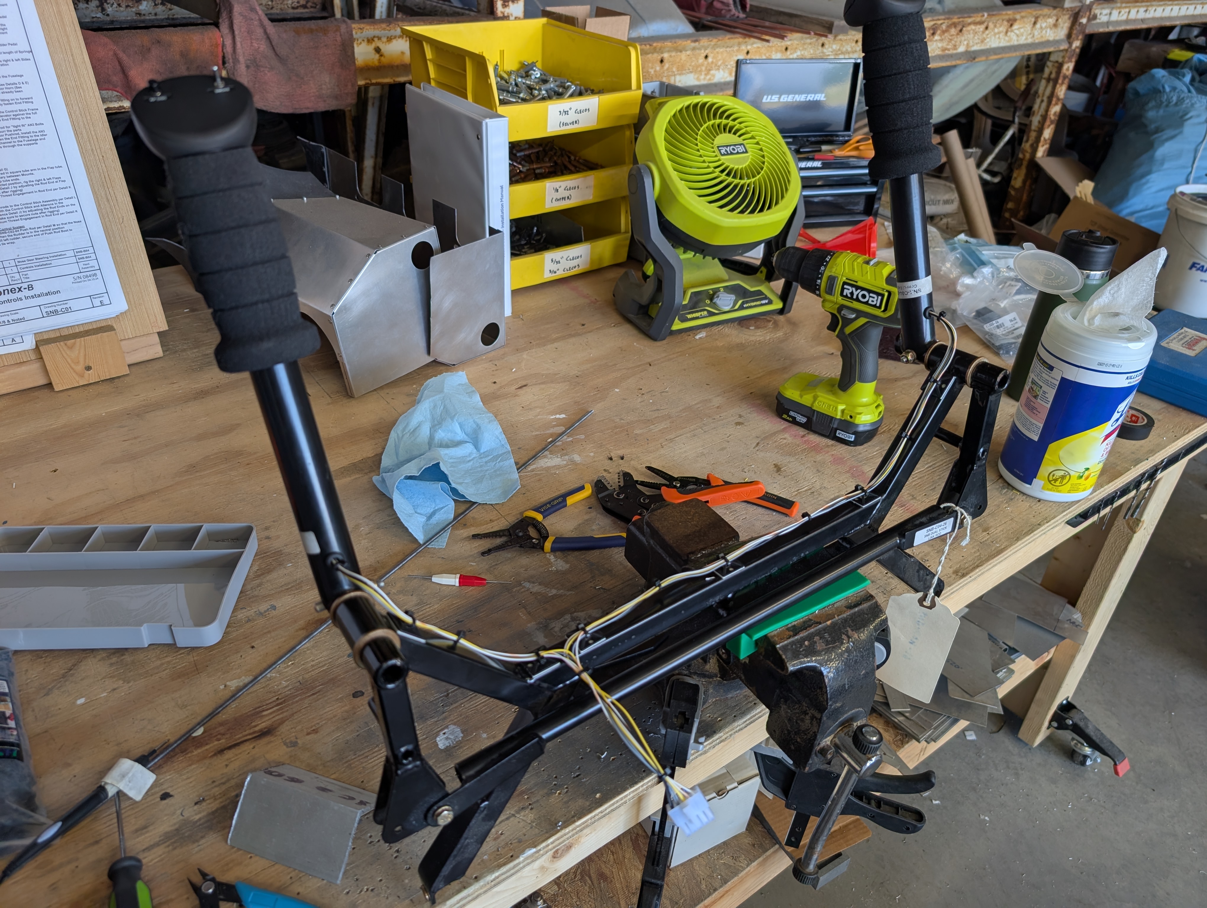
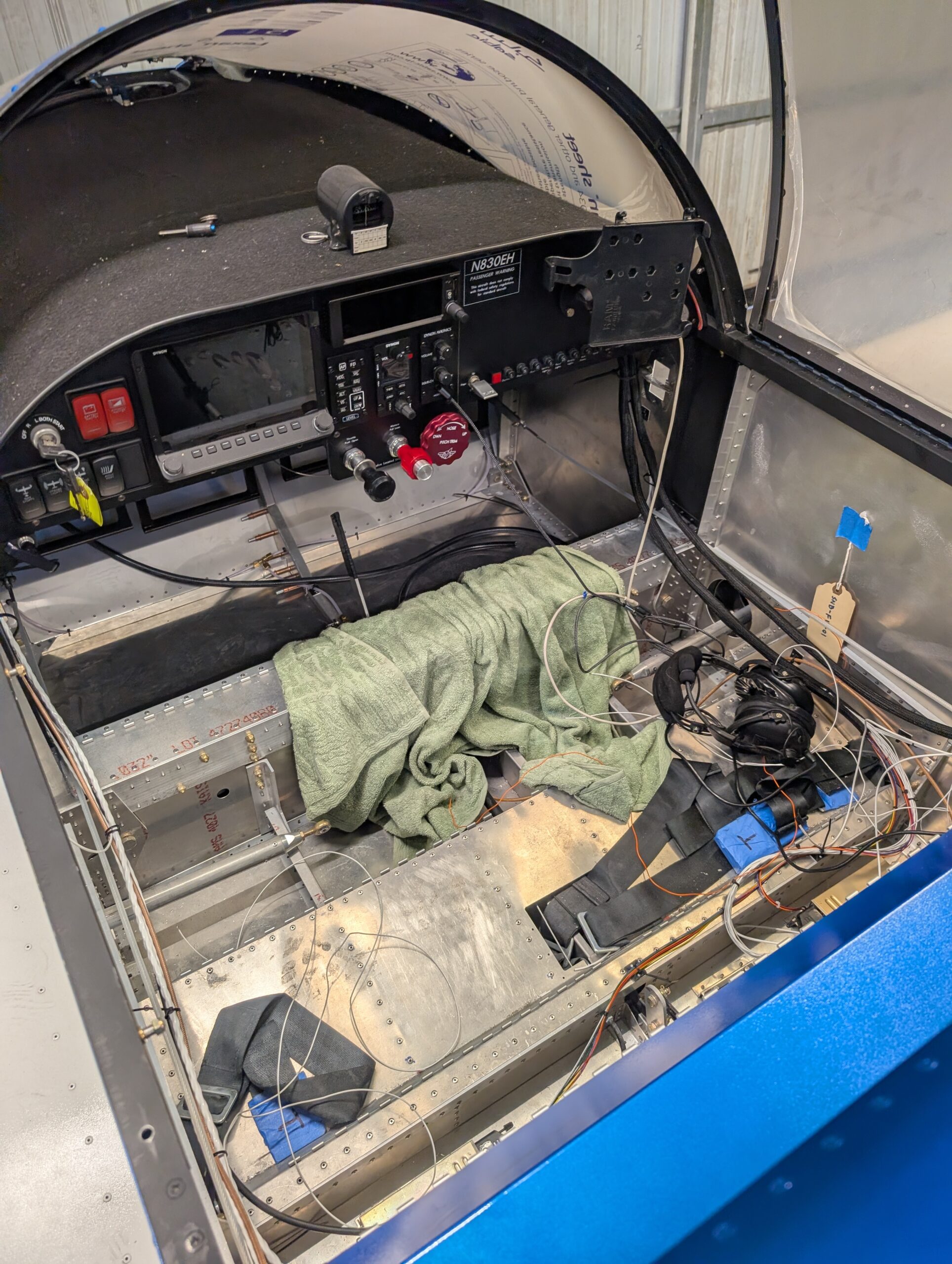
Stick Grip Installation
Finished securing wiring behind instrument panel and underneath sub-panel shelf. Drilled wire hole in bottom of both control sticks for stick grip wiring. Aligned stick grips and drilled pilot hole in grip and control stick. Updrilled holes and tapped stick for 8-32 set screw. Installed stick grip foam onto each control stick and fished wires…

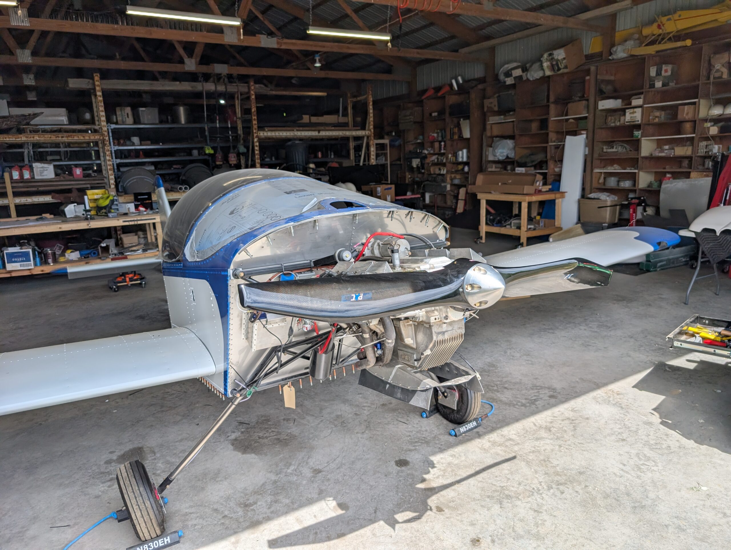
Initial Prop Installation
Began initial prop installation by enlarging holes in Jabiru prop bushings from 1/4″ to 3/8″ using drill press. Verified holes in prop did not need any reaming but needed to ream holes in spinner slightly to allow for smooth bolt installation. Bolted prop and spinner to prop flange using AN6 hardware and AN363 lock nuts.…

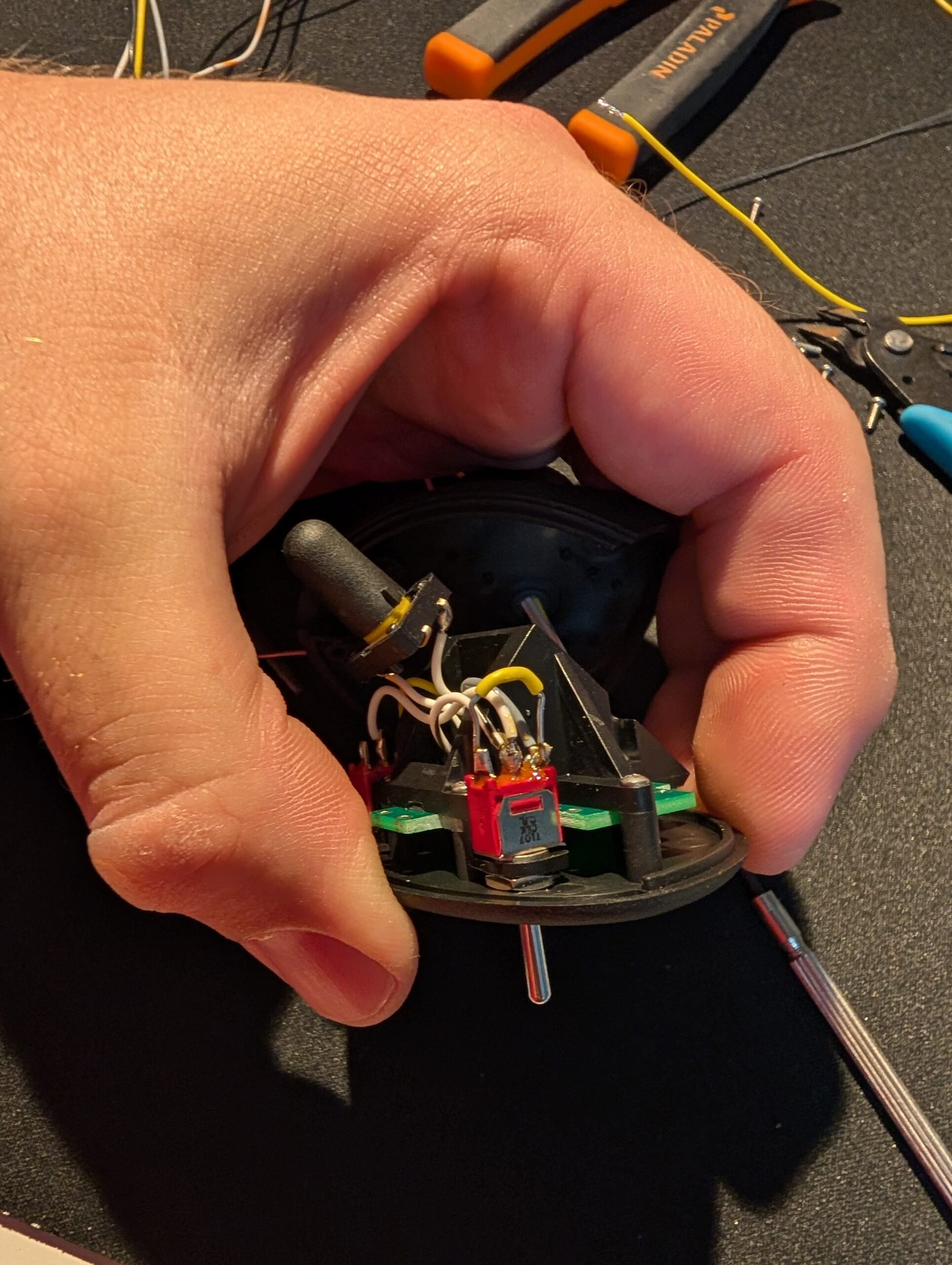
Stick Grip Modification
Opted to modify internal wiring inside the Ray Allen G403 stick grips in order to isolate PTT ground from other function ground. Removed screws in stick grip in order to remove circuit board from plastic housing. The default wiring is set up so that all functions share a common ground and the momentary/latched toggle switch…
Elevator and Rudder Rigging
Connected rudder cables to rudder horn per plans and installed rudder cable fairings on fuselage. Installed hardware for elevator push rod and lubricated bushing with LPS-1. Riveted SNB-F23-09 pushrod assembly to fuselage and verified freedom of movement in elevator control system. Hours Worked: 1.05
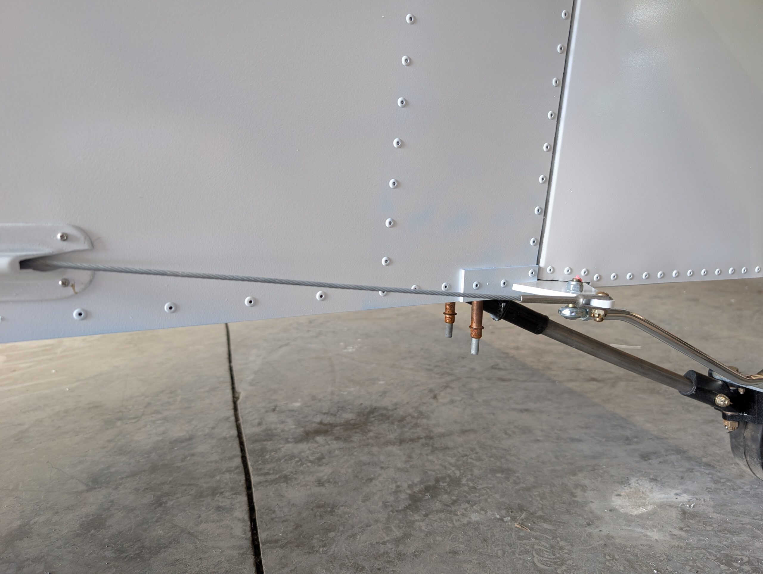
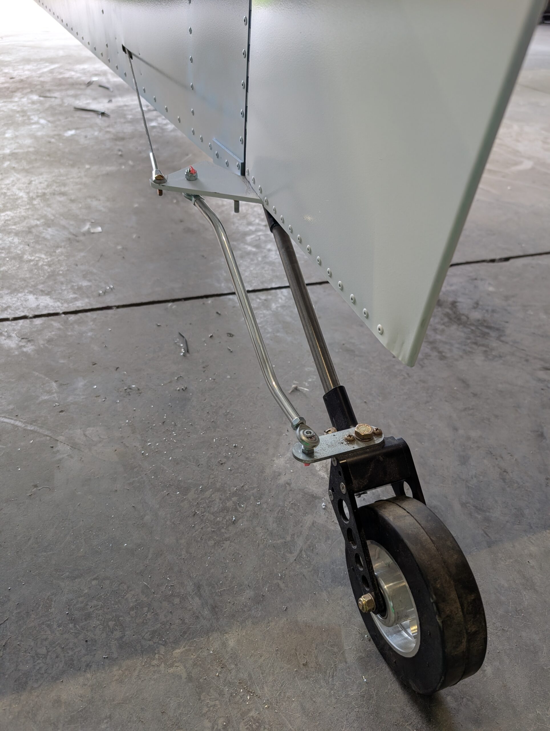
Tailwheel Installation – Part 3
Epoxied tail spring rod into fuselage using 3M DP8407 metal epoxy to strengthen connection since rod had a little bit of play in tail spring mount bracket. Installed tail spring hardware. Upsized steering linkage rod holes in tail wheel assembly and rudder horn then installed Anson Engineering steering rod. Used torque seal on hardware. Hours…
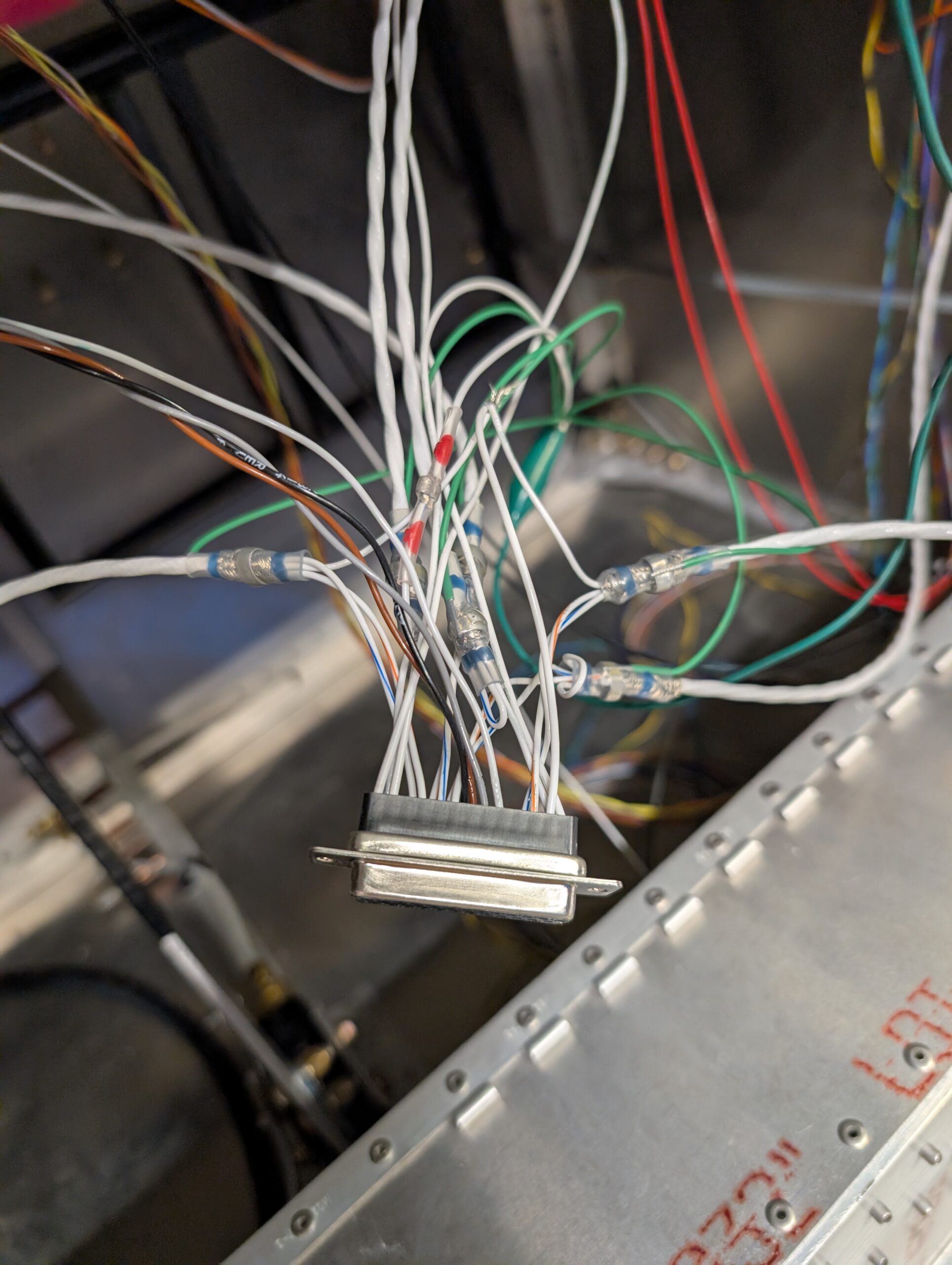
Wiring Cleanup – Part 1
Installed aux power fuse block and SkyView splitter on underside of cross tie box with rivnuts. Worked on organizing and securing wiring under panel with zip ties and adhesive pads. Cut off unused EMS wires and secured into bundle in case of future upgrades. In spots where wire crosses over or under throttle controls, placed…
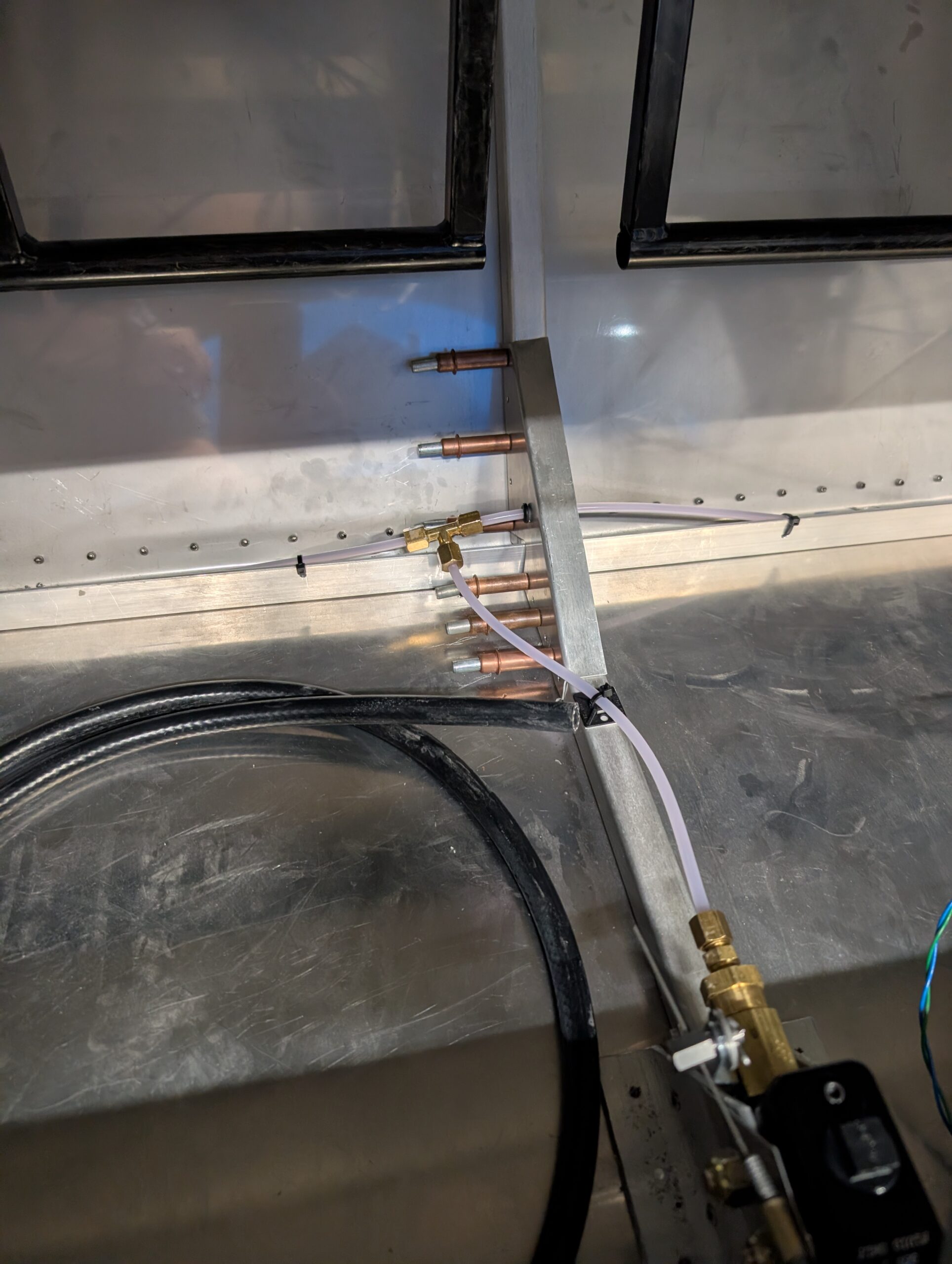
Brake System Assembly – Part 4
Began process of bleeding brakes using traditional pressure method but discovered half way through that tee fitting on cockpit floor was weeping slightly. Removed tubes from tee and installed new couplers on tube. Reattached tubes and tightened fittings by hand tightening compression nuts then further tightening fittings one rotation with a wrench. Applied parking brake…
Intercom Harness Wiring – Part 2
Soldered shielded wire bundles onto copilot headset and passenger jacks. Installed both jacks on copilot side panel and routed wires to main intercom harness. Pinned connects at harness side then tested copilot side audio. Realized the the SkyView audio wires were routed under the throttle cable so had to unpin the four display wires and…
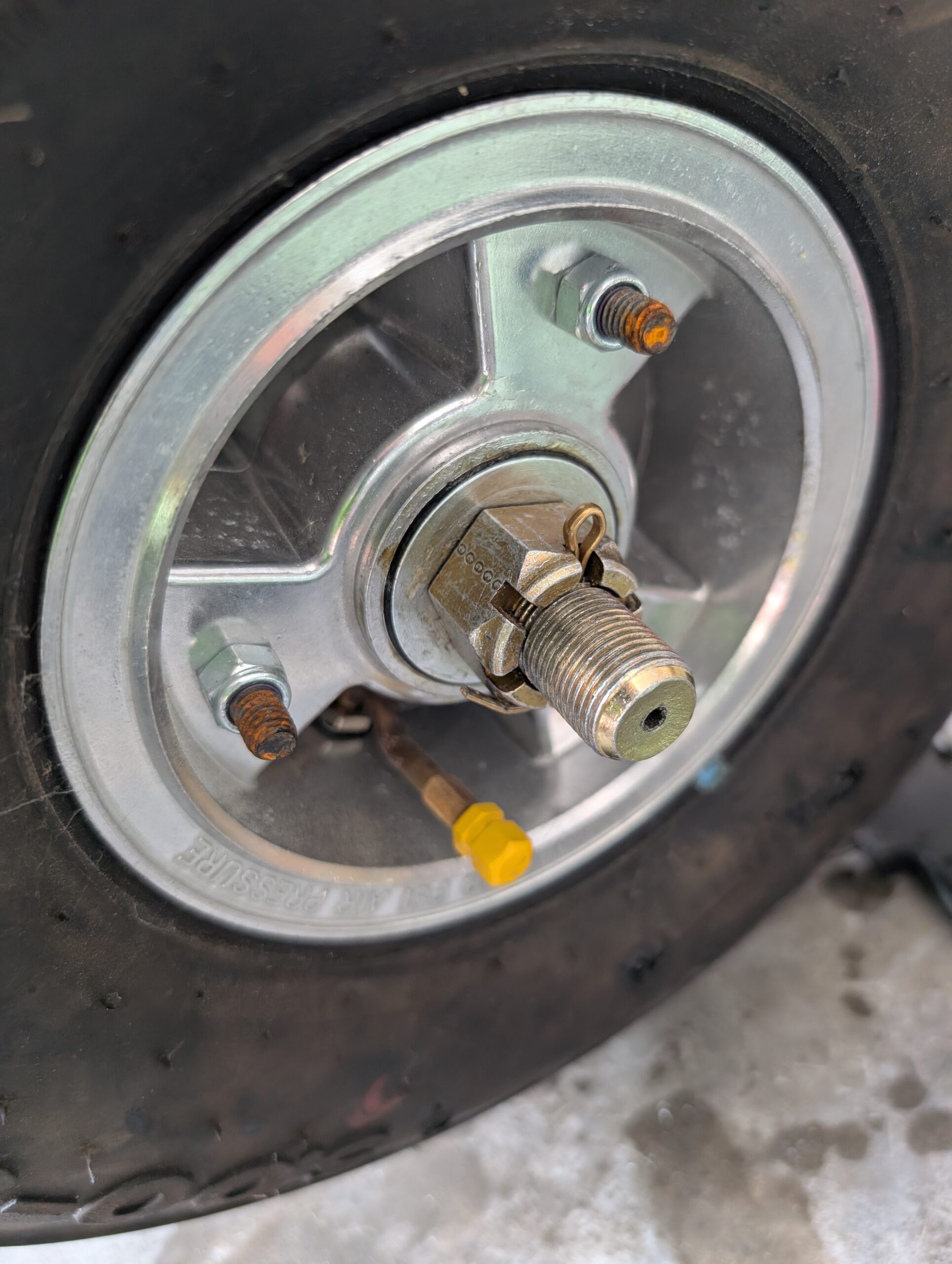
Main Landing Gear Installation – Part 5
After replacing hydraulic brake o-rings, reset axle nut torque by tightening nut until wheel did not wobble and slight resistance was felt on wheel. Marked castle nut location on axle then drilled cotter pin holes using 5/32″ drill bit, cylindrical drill guide, and drilling fluid. After drilling both axles, chased threads with axle nut to…
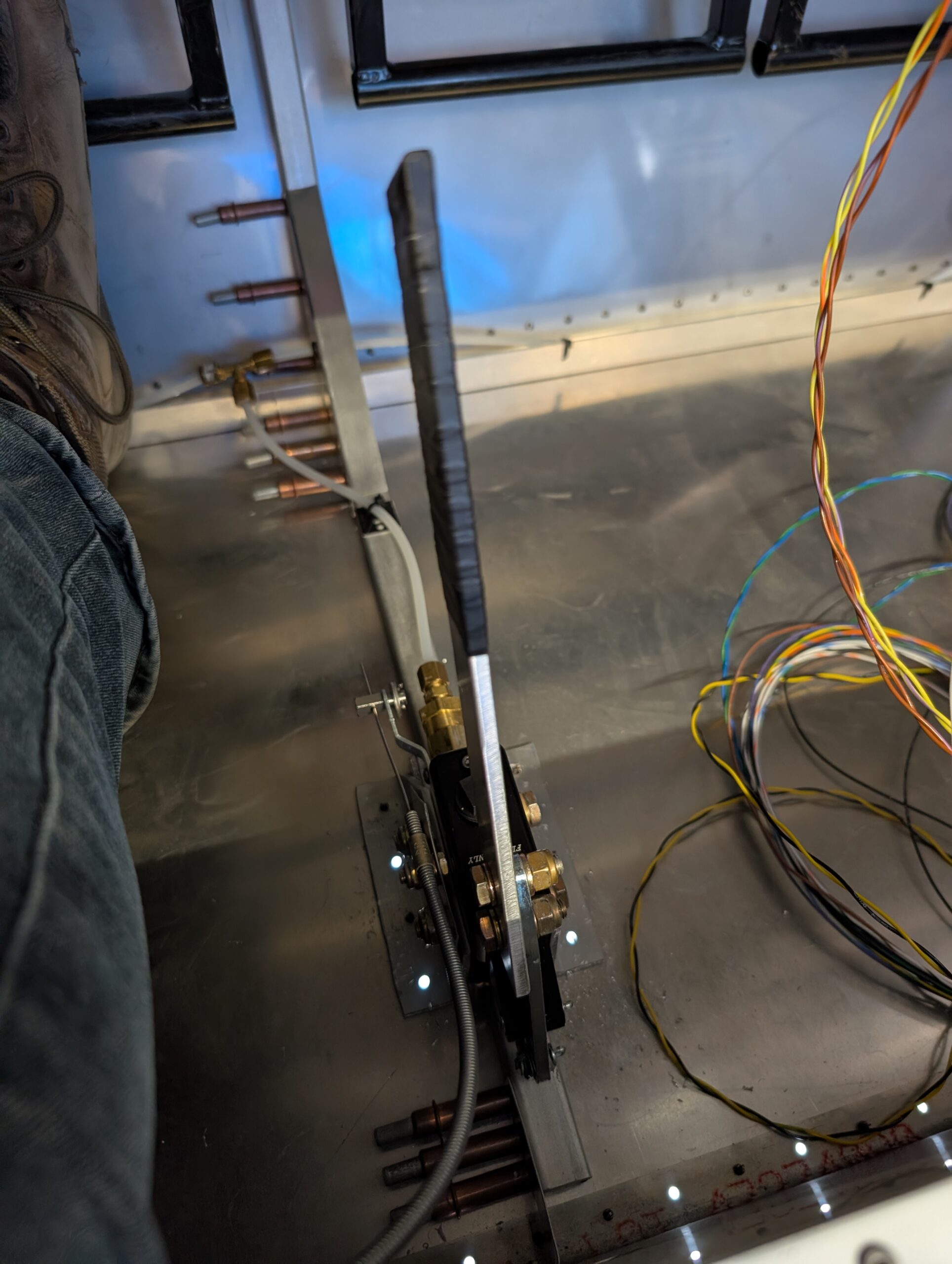
Brake System Assembly – Part 3
Manufactured master cylinder mount components out of aluminum sheet and angle stock. Because the B-Model plans do not have provisions for a center mounted brake lever, used “sport trainer” plan set from the legacy plans for part dimensions. Also substituted two 0.125″ spacer plates on each side of the mounts rather than one 0.25″ piece…
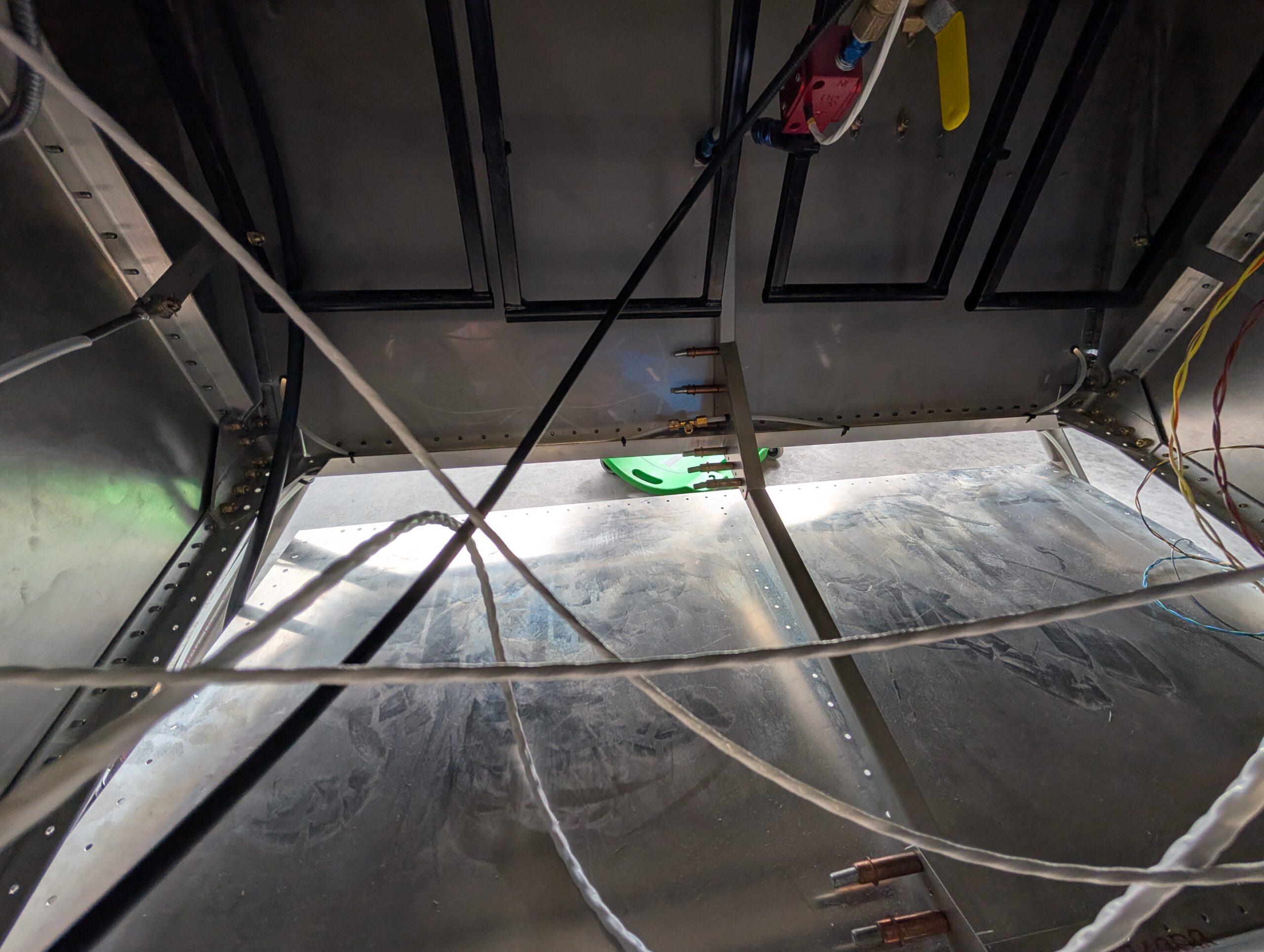
Brake System Assembly – Part 2
Began plumbing brake system by drilling brake line pass throughs in firewall and installing rubber grommets. Routed left and right side brake lines from each wheel end to the tee located in on the forward fuselage floor. Secured brake lines with zip ties to lower fuselage cross member and gear legs. Hours Worked: 1.72
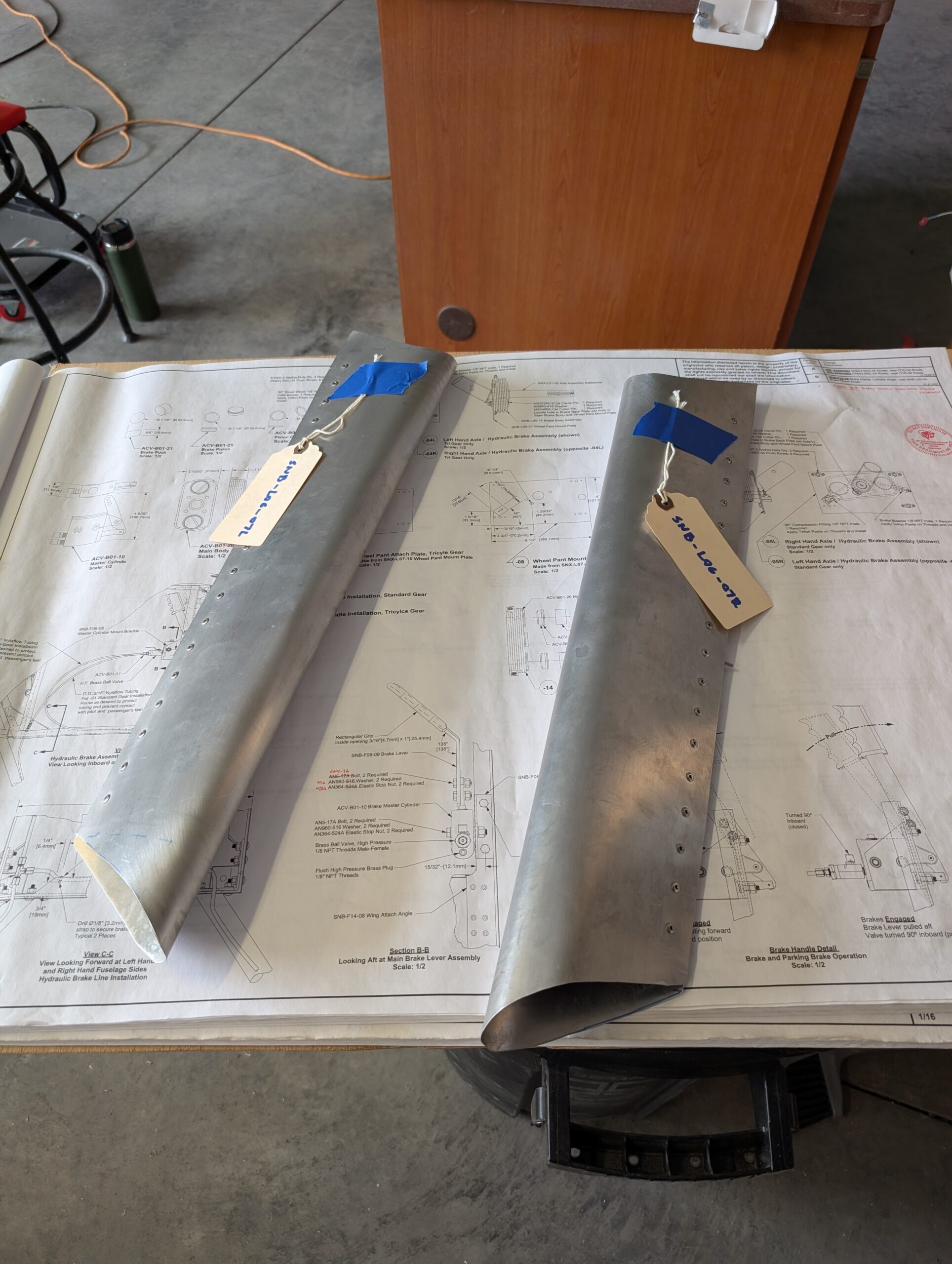
Gear Leg Fairings – Part 1
Fabricated gear leg fairings by transferring plan measurements to 0.025″ aluminum sheet and cutting out fairing skins. Cut and pilot drilled hinge halves from P3 piano hinge stock. Clecoed hinges to fairing skins and bent skins into shape using conduit to help form leading edge radius. Pinned fairings into shape then annealed aluminum using a…